Sony BVME170A User Manual (Operating Instructions - BVM-E250A / BVM-E170A) - Page 21
SDI INPUT 1 connector
 |
View all Sony BVME170A manuals
Add to My Manuals
Save this manual to your list of manuals |
Page 21 highlights
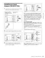
Chapter 1 Overview Pin number 1 2 3 4 5 6, 7 8 9 Function Sets input signal channel 1 (numeric keypad function). Sets input signal channel 2 (numeric keypad function). Selects sync signal (SYNC button function). Selects whether monochrome image is displayed or the monitor switches the display mode automatically between color image and monochrome image depending on the input signal (MONO button function). Marker (set in the Marker Setting menu) On/Off (MARKER button function). Not connected Tally lamp On/Off Ground All pin function assignments can be changed with the Parallel Remote menu (page 82) of the System Configuration menu. To switch each function between On and Off or between enable and disable, change pin connections in the following way. On or enabled: Short each pin and pin 9 together. Off or disabled: Leave each pin open. h STANDARD PORT SDI INPUT 1 connector Inputs serial digital signals (standard SDI input 1). SDI INPUT 2 connector Inputs serial digital signals (standard SDI input 2). MONITOR OUT connector This is the MONITOR OUT connector for SDI INPUT 1 or SDI INPUT 2 connector. Note The signal from this MONITOR OUT connector does not satisfy the ON-LINE signal specifications. i HDMI IN connector Inputs the HDMI signal. HDMI (High-Definition Multimedia Interface) is an interface that supports both video and audio on a single digital connection, allowing you to display high quality digital picture. The HDMI specification supports HDCP (High-bandwidth Digital Content Protection), a copy protection technology that incorporates coding technology for digital video signals. Notes • The HDMI audio signal is not available for this monitor. • Use HDMI compliant cable (optional), Category 2 (High Speed HDMI Cable), with HDMI logo. j DisplayPort input connector Inputs the DisplayPort signal. DisplayPort is an interface developed by VESA that supports transfer of both video and audio digital signals on a single cable. It also supports HDCP, a copy protection technology that incorporates coding technology for digital video signals. Note This monitor does not support DisplayPort audio signals. k Input option ports Used to install the optional input adaptors. For installing the input adaptor, see page 25. For the input signals, see "Input/Output Connectors and Input Adaptors" on page 13. 21 Location and Function of Parts (BVM-E170A)
-
 1
1 -
2
-
3
-
4
-
5
-
6
-
7
-
8
-
9
-
10
-
11
-
12
-
13
-
14
-
15
-
 16
16 -
 17
17 -
 18
18 -
 19
19 -
 20
20 -
 21
21 -
 22
22 -
 23
23 -
 24
24 -
 25
25 -
 26
26 -
27
-
28
-
29
-
30
-
31
-
32
-
33
-
34
-
35
-
36
-
37
-
38
-
39
-
40
-
41
-
42
-
43
-
44
-
45
-
46
-
47
-
48
-
49
-
50
-
51
-
52
-
53
-
54
-
55
-
56
-
57
-
58
-
59
-
60
-
61
-
62
-
63
-
64
-
65
-
66
-
67
-
68
-
69
-
70
-
71
-
72
-
73
-
74
-
75
-
76
-
77
-
78
-
79
-
80
-
81
-
82
-
83
-
84
-
85
-
86
-
87
-
88
-
89
-
90
-
91
-
92
-
93
-
94
-
95
-
96
-
97
-
98
-
99
-
100
-
101
-
102
-
103
-
104
-
105
-
106
-
107
-
108
-
109
-
110
-
111
-
112
-
113
-
114
-
115
-
116
-
117
-
118
-
119
-
120
-
121
-
122
-
123
-
124
-
125
-
126
-
127
-
128
-
129
-
130
-
131
-
132
-
133
-
134
-
135
-
136
-
137
-
138
-
139
-
140
-
141
-
142
-
143
-
144
-
145
-
146
-
147
-
148
-
149
-
150
-
151
-
152
-
153
-
154
-
155
 |
 |
