Sony HCD-E300 Operating Instructions - Page 20
Step 2: Connecting the System, Connecting the speakers - reading
 |
View all Sony HCD-E300 manuals
Add to My Manuals
Save this manual to your list of manuals |
Page 20 highlights
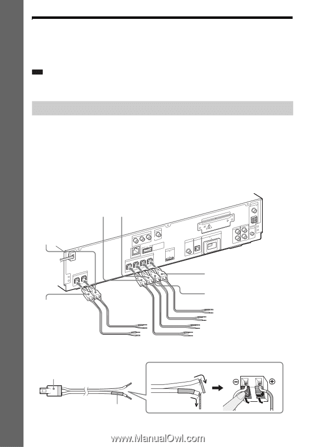
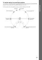
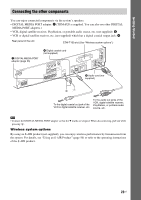
Getting Started Step 2: Connecting the System For connecting the system, read the information on the following pages. Do not connect the AC power cord (mains lead) of the unit to a wall outlet (mains) until all the other connections are made. Note • When you connect another component with a volume control, turn down the volume of the other components to a level where sound is not distorted. Connecting the speakers The connector of the speaker cords and the color tube are color-coded depending on the type of speaker. Connect the speaker cords to match the color of the SPEAKER jacks of the unit. Be sure to match the speaker cords to the appropriate terminals on the speakers: the speaker cord with the color tube to 3, and the speaker cord without the color tube to #. Do not catch the speaker cord insulation (rubber covering) in the speaker terminals. To connect speaker cords to the unit When connecting to the unit, insert the connector until it clicks. Rear panel of the unit Red White (Front right speaker (R)) (Front left speaker (L)) Purple (Subwoofer) SPEAKER CENTER SUBWOOFER COMPONENT VIDEO OUT PR / CR PB / CB Y LAN(1S0PE0A)KER VIDEO OUT HDMI OUT DMPORT D70C05mVA MAX FRONT R FRONT L SUR R SUR L Green (Center speaker) EZW-T100 SDAIGT/ICTAALBLINE TV DIGITAL IN DC5V EXT 500mA MAX COAXIAL OPTICAL COAAXNITAELN7N5 A FM TV L R AUDIO IN AUDIO L AM AE.CCMAL-AMCI2C R AUDIO IN Blue (Surround left speaker (L)) Gray (Surround right speaker (R)) To connect speaker cords to the speaker Connector (-) 20US Color tube (+) Rear of the speaker
-
 1
1 -
2
-
3
-
4
-
5
-
6
-
7
-
8
-
9
-
10
-
11
-
12
-
13
-
14
-
 15
15 -
 16
16 -
 17
17 -
 18
18 -
 19
19 -
 20
20 -
 21
21 -
 22
22 -
 23
23 -
 24
24 -
 25
25 -
26
-
27
-
28
-
29
-
30
-
31
-
32
-
33
-
34
-
35
-
36
-
37
-
38
-
39
-
40
-
41
-
42
-
43
-
44
-
45
-
46
-
47
-
48
-
49
-
50
-
51
-
52
-
53
-
54
-
55
-
56
-
57
-
58
-
59
-
60
-
61
-
62
-
63
-
64
-
65
-
66
-
67
-
68
-
69
-
70
-
71
-
72
-
73
-
74
-
75
-
76
-
77
-
78
-
79
-
80
-
81
-
82
-
83
-
84
-
85
-
86
-
87
-
88
-
89
-
90
-
91
-
92
-
93
-
94
-
95
-
96
-
97
-
98
-
99
-
100
-
101
-
102
-
103
-
104
-
105
-
106
-
107
-
108
-
109
-
110
-
111
-
112
-
113
-
114
-
115
-
116
-
117
-
118
-
119
 |
 |