Toro 20330 Service Manual - Page 103
Under Deck Components Assembly Toro, Vacu Power/Lawn-Boy Medallion
 |
UPC - 021038203300
View all Toro 20330 manuals
Add to My Manuals
Save this manual to your list of manuals |
Page 103 highlights
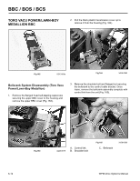
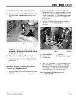
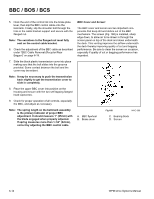
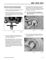
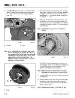
BBC / BOS / BCS Under Deck Components Assembly (Toro Vacu Power/Lawn-Boy Medallion) 1. Check to make sure that the brake plate seal is in good condition, then stretch onto the brake plate bushing (Fig. 173). 3. Loosely secure the brake plate, complete with brake pad, to the brake lever and brake hub as shown in Figure 174. Note that the bolt should go through the brake plate first. Secure with a nylon locknut but do not tighten at this time. This will allow proper alignment of the idler pulley later. A A. Seal B Fig 173 3428-0108 B. Brake plate bushing A. Brake plate A Fig 174 B. Bolt B 3428-0101 2. Hook the control link into the slot on the brake lever. Place the spring and bushing onto the brake rod, then slip the bushing and brake rod through the hole provided in the brake lever. Finally, install the bushing hub and flanged head self-tapping screw with the washer through the brake lever. Note: Brake plate capscrew torque: 225 in-lbs. (25.5 Nm) Note: If the self-tapping screw strips the threads in the housing, do not helicoil; rather, place a hex nut in the recess provided in the top side of the deck. 4. Install an idler hub into each side of the idler pulley bearing, then slip the belt onto the idler pulley. Slip the entire assembly between the brake plate and brake lever. Secure the carriage bolt and nylon locknut as shown in Figure 174. 5. Tighten the idler pulley bolt. Make sure that the idler pulley spins freely. Note: Idler pulley bolt torque: 100 in-lbs. (11.33 Nm) WPM Drive Systems Manual 6-17
-
 1
1 -
2
-
3
-
4
-
5
-
6
-
7
-
8
-
9
-
10
-
11
-
12
-
13
-
14
-
15
-
16
-
17
-
18
-
19
-
20
-
21
-
22
-
23
-
24
-
25
-
26
-
27
-
28
-
29
-
30
-
31
-
32
-
33
-
34
-
35
-
36
-
37
-
38
-
39
-
40
-
41
-
42
-
43
-
44
-
45
-
46
-
47
-
48
-
49
-
50
-
51
-
52
-
53
-
54
-
55
-
56
-
57
-
58
-
59
-
60
-
61
-
62
-
63
-
64
-
65
-
66
-
67
-
68
-
69
-
70
-
71
-
72
-
73
-
74
-
75
-
76
-
77
-
78
-
79
-
80
-
81
-
82
-
83
-
84
-
85
-
86
-
87
-
88
-
89
-
90
-
91
-
92
-
93
-
94
-
95
-
96
-
97
-
 98
98 -
 99
99 -
 100
100 -
 101
101 -
 102
102 -
 103
103 -
 104
104 -
 105
105 -
 106
106 -
 107
107 -
 108
108 -
109
-
110
-
111
-
112
-
113
-
114
-
115
-
116
-
117
-
118
-
119
-
120
-
121
-
122
-
123
-
124
-
125
-
126
-
127
-
128
-
129
-
130
-
131
-
132
-
133
-
134
-
135
-
136
-
137
-
138
-
139
-
140
-
141
-
142
-
143
-
144
 |
 |
