Toro 20330 Service Manual - Page 50
A. Stop cable - carburetor
 |
UPC - 021038203300
View all Toro 20330 manuals
Add to My Manuals
Save this manual to your list of manuals |
Page 50 highlights
SINGLE SPEED BEVEL GEAR TRANSMISSION 8. Push it into the larger hole (Fig. 066). 11. Pinch the ends of the lower handle together to disengage them from the pins on the HOC plates (Fig. 068). Fig 066 PICT-1897 9. Remove both rear wheels and both wheel covers. 10. Remove the stop cable from the engine (Fig. 067) and disconnect the self propel cable spring from the transmission. Fig 068 MVC-737 12. Tip the mower onto its right side (carburetor up) and remove the blade. 13. Remove one of the belt guide screws and loosen the other enough to pivot the guide away (Fig. 069). Do not bend the belt guide. Slide the pulley/blade adapter and belt off the crankshaft. A A. Stop cable Fig 067 DSC-017 3-12 Fig 069 MVC-738 WPM Drive Systems Manual
-
 1
1 -
2
-
3
-
4
-
5
-
6
-
7
-
8
-
9
-
10
-
11
-
12
-
13
-
14
-
15
-
16
-
17
-
18
-
19
-
20
-
21
-
22
-
23
-
24
-
25
-
26
-
27
-
28
-
29
-
30
-
31
-
32
-
33
-
34
-
35
-
36
-
37
-
38
-
39
-
40
-
41
-
42
-
43
-
44
-
 45
45 -
 46
46 -
 47
47 -
 48
48 -
 49
49 -
 50
50 -
 51
51 -
 52
52 -
 53
53 -
 54
54 -
 55
55 -
56
-
57
-
58
-
59
-
60
-
61
-
62
-
63
-
64
-
65
-
66
-
67
-
68
-
69
-
70
-
71
-
72
-
73
-
74
-
75
-
76
-
77
-
78
-
79
-
80
-
81
-
82
-
83
-
84
-
85
-
86
-
87
-
88
-
89
-
90
-
91
-
92
-
93
-
94
-
95
-
96
-
97
-
98
-
99
-
100
-
101
-
102
-
103
-
104
-
105
-
106
-
107
-
108
-
109
-
110
-
111
-
112
-
113
-
114
-
115
-
116
-
117
-
118
-
119
-
120
-
121
-
122
-
123
-
124
-
125
-
126
-
127
-
128
-
129
-
130
-
131
-
132
-
133
-
134
-
135
-
136
-
137
-
138
-
139
-
140
-
141
-
142
-
143
-
144
 |
 |

3-12
WPM Drive Systems Manual
SINGLE SPEED BEVEL GEAR TRANSMISSION
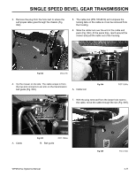
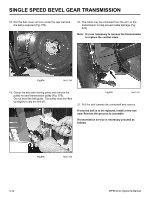
12. Tip the mower onto its right side (carburetor up) and
remove the blade.
13. Remove one of the belt guide screws and loosen
the other enough to pivot the guide away (Fig. 069).
Do not bend the belt guide. Slide the pulley/blade
adapter and belt off the crankshaft.
Fig 069
MVC-738
Fig 066
PICT-1897
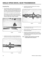
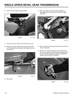
8.
Push it into the larger hole (Fig. 066).
9.
Remove both rear wheels and both wheel covers.
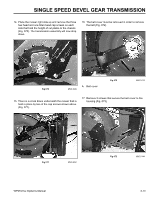
10. Remove the stop cable from the engine (Fig. 067)
and disconnect the self propel cable spring from the
transmission.
Fig 067
DSC-017
Fig 068
MVC-737
11. Pinch the ends of the lower handle together to
disengage them from the pins on the HOC plates
(Fig. 068).
A. Stop cable
A