Toro 20330 Service Manual - Page 44
end of the axle the left side has 2 thrust washers
 |
UPC - 021038203300
View all Toro 20330 manuals
Add to My Manuals
Save this manual to your list of manuals |
Page 44 highlights
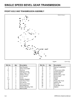
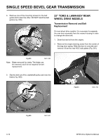
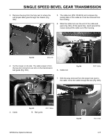
SINGLE SPEED BEVEL GEAR TRANSMISSION 9. Remove the two bolts and nuts securing each pivot arm to the housing. There is a notch in the pivot arm for clearance of a socket (Fig. 045). 10. Remove the klip ring and thrust washer from each end of the axle (the left side has 2 thrust washers, the right side, one). The bearing, bearing retainer, HOC plate, spring arm and pivot arm all come off as one unit (Fig. 047). Fig 045 MVC-475 The axle assembly will now drop out of the chassis (Fig. 046). Fig 047 PICT-1858a 11. To disassemble the pivot arm assembly, compress the components with two clamps or locking pliers (Fig. 048). Fig 046 PICT-1857a 3-6 Fig 048 MVC-478 WPM Drive Systems Manual
-
 1
1 -
2
-
3
-
4
-
5
-
6
-
7
-
8
-
9
-
10
-
11
-
12
-
13
-
14
-
15
-
16
-
17
-
18
-
19
-
20
-
21
-
22
-
23
-
24
-
25
-
26
-
27
-
28
-
29
-
30
-
31
-
32
-
33
-
34
-
35
-
36
-
37
-
38
-
 39
39 -
 40
40 -
 41
41 -
 42
42 -
 43
43 -
 44
44 -
 45
45 -
 46
46 -
 47
47 -
 48
48 -
 49
49 -
50
-
51
-
52
-
53
-
54
-
55
-
56
-
57
-
58
-
59
-
60
-
61
-
62
-
63
-
64
-
65
-
66
-
67
-
68
-
69
-
70
-
71
-
72
-
73
-
74
-
75
-
76
-
77
-
78
-
79
-
80
-
81
-
82
-
83
-
84
-
85
-
86
-
87
-
88
-
89
-
90
-
91
-
92
-
93
-
94
-
95
-
96
-
97
-
98
-
99
-
100
-
101
-
102
-
103
-
104
-
105
-
106
-
107
-
108
-
109
-
110
-
111
-
112
-
113
-
114
-
115
-
116
-
117
-
118
-
119
-
120
-
121
-
122
-
123
-
124
-
125
-
126
-
127
-
128
-
129
-
130
-
131
-
132
-
133
-
134
-
135
-
136
-
137
-
138
-
139
-
140
-
141
-
142
-
143
-
144
 |
 |

3-6
WPM Drive Systems Manual
SINGLE SPEED BEVEL GEAR TRANSMISSION
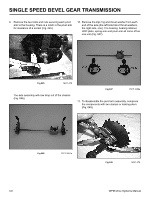
9.
Remove the two bolts and nuts securing each pivot
arm to the housing. There is a notch in the pivot arm
for clearance of a socket (Fig. 045).
Fig 045
MVC-475
The axle assembly will now drop out of the chassis
(Fig. 046).
Fig 046
PICT-1857a
Fig 048
MVC-478
11. To disassemble the pivot arm assembly, compress
the components with two clamps or locking pliers
(Fig. 048).
10. Remove the klip ring and thrust washer from each
end of the axle (the left side has 2 thrust washers,
the right side, one). The bearing, bearing retainer,
HOC plate, spring arm and pivot arm all come off as
one unit (Fig. 047).
Fig 047
PICT-1858a