Toro 20330 Service Manual - Page 51
A. Belt cover
 |
UPC - 021038203300
View all Toro 20330 manuals
Add to My Manuals
Save this manual to your list of manuals |
Page 51 highlights
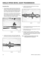
SINGLE SPEED BEVEL GEAR TRANSMISSION 14. Place the mower right side up and remove the three hex head and one Allen head cap screws on each side that hold the height of cut plates to the chassis (Fig. 070). The transmission assembly will now drop down. 16. The belt cover must be removed in order to remove the belt (Fig. 072). A Fig 070 MVC-848 A. Belt cover Fig 072 MVC-743 15. There is a cross brace underneath the mower that is held in place by two of the cap screws shown above (Fig. 071). 17. Remove 3 screws that secure the belt cover to the housing (Fig. 073). Fig 071 MVC-852 WPM Drive Systems Manual Fig 073 MVC-744 3-13
-
 1
1 -
2
-
3
-
4
-
5
-
6
-
7
-
8
-
9
-
10
-
11
-
12
-
13
-
14
-
15
-
16
-
17
-
18
-
19
-
20
-
21
-
22
-
23
-
24
-
25
-
26
-
27
-
28
-
29
-
30
-
31
-
32
-
33
-
34
-
35
-
36
-
37
-
38
-
39
-
40
-
41
-
42
-
43
-
44
-
45
-
 46
46 -
 47
47 -
 48
48 -
 49
49 -
 50
50 -
 51
51 -
 52
52 -
 53
53 -
 54
54 -
 55
55 -
 56
56 -
57
-
58
-
59
-
60
-
61
-
62
-
63
-
64
-
65
-
66
-
67
-
68
-
69
-
70
-
71
-
72
-
73
-
74
-
75
-
76
-
77
-
78
-
79
-
80
-
81
-
82
-
83
-
84
-
85
-
86
-
87
-
88
-
89
-
90
-
91
-
92
-
93
-
94
-
95
-
96
-
97
-
98
-
99
-
100
-
101
-
102
-
103
-
104
-
105
-
106
-
107
-
108
-
109
-
110
-
111
-
112
-
113
-
114
-
115
-
116
-
117
-
118
-
119
-
120
-
121
-
122
-
123
-
124
-
125
-
126
-
127
-
128
-
129
-
130
-
131
-
132
-
133
-
134
-
135
-
136
-
137
-
138
-
139
-
140
-
141
-
142
-
143
-
144
 |
 |

3-13
WPM Drive Systems Manual
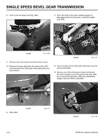
14. Place the mower right side up and remove the three
hex head and one Allen head cap screws on each
side that hold the height of cut plates to the chassis
(Fig. 070). The transmission assembly will now drop
down.
Fig 070
MVC-848
Fig 072
MVC-743
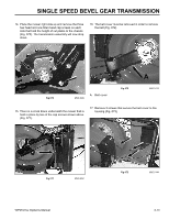
16. The belt cover must be removed in order to remove
the belt (Fig. 072).
Fig 071
MVC-852
15. There is a cross brace underneath the mower that is
held in place by two of the cap screws shown above
(Fig. 071).
SINGLE SPEED BEVEL GEAR TRANSMISSION
17. Remove 3 screws that secure the belt cover to the
housing (Fig. 073).
Fig 073
MVC-744
A
A. Belt cover