Toro 20330 Service Manual - Page 53
Rear Axle Disassembly
 |
UPC - 021038203300
View all Toro 20330 manuals
Add to My Manuals
Save this manual to your list of manuals |
Page 53 highlights
SINGLE SPEED BEVEL GEAR TRANSMISSION Rear Axle Disassembly 1. Remove the klip rings and thrust washers that secure the pinions to the axle (Fig. 077). 4. The pivot assembly will slide off the axle. This includes the bearing, bearing retainer, HOC plate, spring arm, and pivot arm (Fig. 079). Fig 077 MVC-746 Fig 079 MVC-747 2. When removing the pinions, note that there is a spring-loaded key under them. 3. Remove the other thrust washer and retaining ring holding the pivot assembly to the axle (Fig. 078). 5. Clamp the pivot assembly with 2 pairs of locking pliers or other clamps and remove the snap ring (Fig. 080). Fig 078 MVC-850 WPM Drive Systems Manual Fig 080 MVC-748 3-15
-
 1
1 -
2
-
3
-
4
-
5
-
6
-
7
-
8
-
9
-
10
-
11
-
12
-
13
-
14
-
15
-
16
-
17
-
18
-
19
-
20
-
21
-
22
-
23
-
24
-
25
-
26
-
27
-
28
-
29
-
30
-
31
-
32
-
33
-
34
-
35
-
36
-
37
-
38
-
39
-
40
-
41
-
42
-
43
-
44
-
45
-
46
-
47
-
 48
48 -
 49
49 -
 50
50 -
 51
51 -
 52
52 -
 53
53 -
 54
54 -
 55
55 -
 56
56 -
 57
57 -
 58
58 -
59
-
60
-
61
-
62
-
63
-
64
-
65
-
66
-
67
-
68
-
69
-
70
-
71
-
72
-
73
-
74
-
75
-
76
-
77
-
78
-
79
-
80
-
81
-
82
-
83
-
84
-
85
-
86
-
87
-
88
-
89
-
90
-
91
-
92
-
93
-
94
-
95
-
96
-
97
-
98
-
99
-
100
-
101
-
102
-
103
-
104
-
105
-
106
-
107
-
108
-
109
-
110
-
111
-
112
-
113
-
114
-
115
-
116
-
117
-
118
-
119
-
120
-
121
-
122
-
123
-
124
-
125
-
126
-
127
-
128
-
129
-
130
-
131
-
132
-
133
-
134
-
135
-
136
-
137
-
138
-
139
-
140
-
141
-
142
-
143
-
144
 |
 |

3-15
WPM Drive Systems Manual
SINGLE SPEED BEVEL GEAR TRANSMISSION
Rear Axle Disassembly
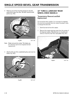
1.
Remove the klip rings and thrust washers that
secure the pinions to the axle (Fig. 077).
Fig 077
MVC-746
Fig 079
MVC-747
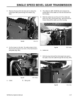
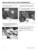
4.
The pivot assembly will slide off the axle. This
includes the bearing, bearing retainer, HOC plate,
spring arm, and pivot arm (Fig. 079).
Fig 078
MVC-850
2.
When removing the pinions, note that there is a
spring-loaded key under them.
3.
Remove the other thrust washer and retaining ring
holding the pivot assembly to the axle (Fig. 078).
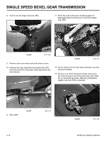
5.
Clamp the pivot assembly with 2 pairs of locking
pliers or other clamps and remove the snap ring
(Fig. 080).
Fig 080
MVC-748