Toro 20330 Service Manual - Page 93
Control Box Assembly
 |
UPC - 021038203300
View all Toro 20330 manuals
Add to My Manuals
Save this manual to your list of manuals |
Page 93 highlights
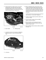
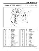
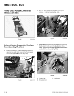
BBC / BOS / BCS A better method is to make a special cut-away version of the right control box housing half as shown in Figure 154. When this cut-away version is installed, all components will function normally. Notice the cut-away cover and how it houses the leaf spring. This will aid in diagnosis. 12. Pull the tape from the outside of the handle. Remove the upper carriage bolt along with the cable lever and spacer. 13. Remove the lower carriage bolt and remove the left control housing. 14. Inspect all parts for wear and/or damage and replace as required. A. Leaf spring A Fig 154 3428-0289b Control Box Assembly 1. Slip the lower carriage bolt through the handle, then slide the left control housing onto it. 2. Slip the end of the traction cable into the traction lever. Place the control housing, traction lever, and the control bar into position as shown in Figure 155. Once in position, slide the carriage bolt through all three components. 6. If further disassembly is required, remove the buckling spring and washer from the rocker arm assembly. 7. Remove the BBC cable from the BBC cable lever and the left-hand control box half. 8. Remove the rocker arm as an assembly, complete with cable lever and control hook. 9. Remove the cable lever from the rocker arm assembly. 10. Press the roll pin from the rocker arm and remove the control hook and torsion spring. 11. Remove the traction cable from the traction lever and the left-hand control housing. A. Leaf spring B. Traction lever Fig 155 C. Traction cable fig 34 WPM Drive Systems Manual 6-7
-
 1
1 -
2
-
3
-
4
-
5
-
6
-
7
-
8
-
9
-
10
-
11
-
12
-
13
-
14
-
15
-
16
-
17
-
18
-
19
-
20
-
21
-
22
-
23
-
24
-
25
-
26
-
27
-
28
-
29
-
30
-
31
-
32
-
33
-
34
-
35
-
36
-
37
-
38
-
39
-
40
-
41
-
42
-
43
-
44
-
45
-
46
-
47
-
48
-
49
-
50
-
51
-
52
-
53
-
54
-
55
-
56
-
57
-
58
-
59
-
60
-
61
-
62
-
63
-
64
-
65
-
66
-
67
-
68
-
69
-
70
-
71
-
72
-
73
-
74
-
75
-
76
-
77
-
78
-
79
-
80
-
81
-
82
-
83
-
84
-
85
-
86
-
87
-
 88
88 -
 89
89 -
 90
90 -
 91
91 -
 92
92 -
 93
93 -
 94
94 -
 95
95 -
 96
96 -
 97
97 -
 98
98 -
99
-
100
-
101
-
102
-
103
-
104
-
105
-
106
-
107
-
108
-
109
-
110
-
111
-
112
-
113
-
114
-
115
-
116
-
117
-
118
-
119
-
120
-
121
-
122
-
123
-
124
-
125
-
126
-
127
-
128
-
129
-
130
-
131
-
132
-
133
-
134
-
135
-
136
-
137
-
138
-
139
-
140
-
141
-
142
-
143
-
144
 |
 |
