Toro 20330 Service Manual - Page 52
If only the belt is to be replaced, install a new one - service manual
 |
UPC - 021038203300
View all Toro 20330 manuals
Add to My Manuals
Save this manual to your list of manuals |
Page 52 highlights
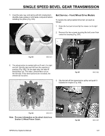
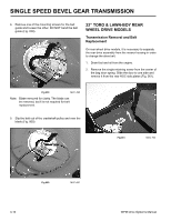
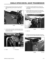
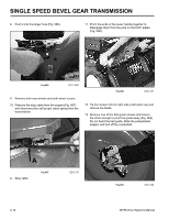
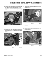
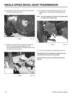
SINGLE SPEED BEVEL GEAR TRANSMISSION 18. Pull the belt cover out from under the rear wall and the belt is exposed (Fig. 074). 20. The cable may be unhooked from the arm on the transmission to help prevent cable damage (Fig. 076). Note: It is not necessary to remove the transmission to replace the control cable. Fig 074 MVC-745 19. Clamp the axle with locking pliers and remove the pulley nut and transmission pulley (Fig. 075). Do not bend the belt guide. The pulley must be lifted up slightly to slip the belt off. Fig 076 MVC-741 21. Pull the belt towards the crankshaft and remove. If only the belt is to be replaced, install a new one now. Reverse the process to assemble. If transmission service is necessary proceed as follows. Fig 075 MVC-740 3-14 WPM Drive Systems Manual
-
 1
1 -
2
-
3
-
4
-
5
-
6
-
7
-
8
-
9
-
10
-
11
-
12
-
13
-
14
-
15
-
16
-
17
-
18
-
19
-
20
-
21
-
22
-
23
-
24
-
25
-
26
-
27
-
28
-
29
-
30
-
31
-
32
-
33
-
34
-
35
-
36
-
37
-
38
-
39
-
40
-
41
-
42
-
43
-
44
-
45
-
46
-
 47
47 -
 48
48 -
 49
49 -
 50
50 -
 51
51 -
 52
52 -
 53
53 -
 54
54 -
 55
55 -
 56
56 -
 57
57 -
58
-
59
-
60
-
61
-
62
-
63
-
64
-
65
-
66
-
67
-
68
-
69
-
70
-
71
-
72
-
73
-
74
-
75
-
76
-
77
-
78
-
79
-
80
-
81
-
82
-
83
-
84
-
85
-
86
-
87
-
88
-
89
-
90
-
91
-
92
-
93
-
94
-
95
-
96
-
97
-
98
-
99
-
100
-
101
-
102
-
103
-
104
-
105
-
106
-
107
-
108
-
109
-
110
-
111
-
112
-
113
-
114
-
115
-
116
-
117
-
118
-
119
-
120
-
121
-
122
-
123
-
124
-
125
-
126
-
127
-
128
-
129
-
130
-
131
-
132
-
133
-
134
-
135
-
136
-
137
-
138
-
139
-
140
-
141
-
142
-
143
-
144
 |
 |
