Toro 20330 Service Manual - Page 111
Idler Arm System Assembly Recycler/Rear, Bagger
 |
UPC - 021038203300
View all Toro 20330 manuals
Add to My Manuals
Save this manual to your list of manuals |
Page 111 highlights
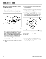
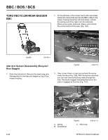
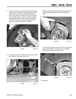
BBC / BOS / BCS Idler Arm System Assembly (Recycler/Rear Bagger) 1. Start by installing the key and self-propel pulley. The two bumps on the pulley should face you (Fig. 193). Slip the belt over the pulley. The flywheel must be installed with the side that looks like 1/2 of a pulley facing the brake drum (Fig. 194). Push the flywheel firmly on the taper of the crankshaft. If you can't push the flywheel on far enough to hold, do not be concerned. DO NOT drive it on with a hammer. A B A. Bumps Fig 193 3428-0117 B. Holes in flywheel 2. Install the flywheel. The two bumps on the pulley MUST engage the holes in the flywheel. If not, when the nut on the crankshaft is tightened, the flywheel will push the pulley upwards, either breaking the wall out of the key groove or crushing the two bumps or both. Fig 194 MVC-727 3. Note the two small foam pads inside the brake drum (Fig. 195). A WPM Drive Systems Manual A. Foam pad Fig 195 3428-0188 6-25
-
 1
1 -
2
-
3
-
4
-
5
-
6
-
7
-
8
-
9
-
10
-
11
-
12
-
13
-
14
-
15
-
16
-
17
-
18
-
19
-
20
-
21
-
22
-
23
-
24
-
25
-
26
-
27
-
28
-
29
-
30
-
31
-
32
-
33
-
34
-
35
-
36
-
37
-
38
-
39
-
40
-
41
-
42
-
43
-
44
-
45
-
46
-
47
-
48
-
49
-
50
-
51
-
52
-
53
-
54
-
55
-
56
-
57
-
58
-
59
-
60
-
61
-
62
-
63
-
64
-
65
-
66
-
67
-
68
-
69
-
70
-
71
-
72
-
73
-
74
-
75
-
76
-
77
-
78
-
79
-
80
-
81
-
82
-
83
-
84
-
85
-
86
-
87
-
88
-
89
-
90
-
91
-
92
-
93
-
94
-
95
-
96
-
97
-
98
-
99
-
100
-
101
-
102
-
103
-
104
-
105
-
 106
106 -
 107
107 -
 108
108 -
 109
109 -
 110
110 -
 111
111 -
 112
112 -
 113
113 -
 114
114 -
 115
115 -
 116
116 -
117
-
118
-
119
-
120
-
121
-
122
-
123
-
124
-
125
-
126
-
127
-
128
-
129
-
130
-
131
-
132
-
133
-
134
-
135
-
136
-
137
-
138
-
139
-
140
-
141
-
142
-
143
-
144
 |
 |
