Toro 20330 Service Manual - Page 55
Axle Assembly Tips
 |
UPC - 021038203300
View all Toro 20330 manuals
Add to My Manuals
Save this manual to your list of manuals |
Page 55 highlights
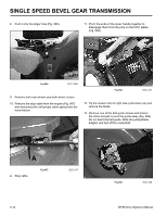
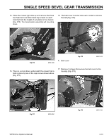
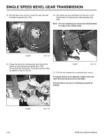
SINGLE SPEED BEVEL GEAR TRANSMISSION Axle Assembly Tips 1. The same axle is used for both front and rear wheel drive models. There are two holes in the axle about one inch apart. Rear wheel drive models use the hole about 4-3/4" (12cm) from the end. Slip the gear on such that the teeth and the longest hub face the short end of the axle. Drive the pin into place. A double check is that neither of the pin holes should be visible when the gear is installed (Fig. 084). 3. Install the transmission bearings with the flange facing the gear (Fig. 085). Fig 085 MVC-470 A. Gear Fig 084 MVC-469 B. Thrust washer 4. Fill the transmission approximately 2/3 full with #2 Lithium base grease (1.5 oz or 43gm). 5. Assemble the bearing, bearing retainer, HOC plate, spring arm, and pivot arm. Use two vise grips or clamps to compress the assembly so the snap ring can be installed (Fig. 086). Note: Install the snap ring with the sharp edge facing away from the spring arm. 2. Install the thrust washer on the side of the gear with the shortest hub, away from the gear teeth (Fig. 084). WPM Drive Systems Manual Fig 086 MVC-748 3-17
-
 1
1 -
2
-
3
-
4
-
5
-
6
-
7
-
8
-
9
-
10
-
11
-
12
-
13
-
14
-
15
-
16
-
17
-
18
-
19
-
20
-
21
-
22
-
23
-
24
-
25
-
26
-
27
-
28
-
29
-
30
-
31
-
32
-
33
-
34
-
35
-
36
-
37
-
38
-
39
-
40
-
41
-
42
-
43
-
44
-
45
-
46
-
47
-
48
-
49
-
 50
50 -
 51
51 -
 52
52 -
 53
53 -
 54
54 -
 55
55 -
 56
56 -
 57
57 -
 58
58 -
 59
59 -
 60
60 -
61
-
62
-
63
-
64
-
65
-
66
-
67
-
68
-
69
-
70
-
71
-
72
-
73
-
74
-
75
-
76
-
77
-
78
-
79
-
80
-
81
-
82
-
83
-
84
-
85
-
86
-
87
-
88
-
89
-
90
-
91
-
92
-
93
-
94
-
95
-
96
-
97
-
98
-
99
-
100
-
101
-
102
-
103
-
104
-
105
-
106
-
107
-
108
-
109
-
110
-
111
-
112
-
113
-
114
-
115
-
116
-
117
-
118
-
119
-
120
-
121
-
122
-
123
-
124
-
125
-
126
-
127
-
128
-
129
-
130
-
131
-
132
-
133
-
134
-
135
-
136
-
137
-
138
-
139
-
140
-
141
-
142
-
143
-
144
 |
 |
