Toro 20330 Service Manual - Page 56
Note: See for more information on Wheel, Clutches.
 |
UPC - 021038203300
View all Toro 20330 manuals
Add to My Manuals
Save this manual to your list of manuals |
Page 56 highlights
SINGLE SPEED BEVEL GEAR TRANSMISSION 6. Coat the axle, key, and spring with #2 molybendum disulfide grease or anti-seize compound before installing the pinion (Fig. 087). Fig 087 MVC-472 7. The wheel pinion is marked with an R and L for right and left. Identify right and left from the operator's position (Fig. 088). On the right side, the R should face outward. The letter L should face outward on the left side. If the wheel pinions are reversed, the wheels will not drive. R Fig 088 MVC-474 Note: See Chapter 5 for more information on Wheel Clutches. 3-18 WPM Drive Systems Manual
-
 1
1 -
2
-
3
-
4
-
5
-
6
-
7
-
8
-
9
-
10
-
11
-
12
-
13
-
14
-
15
-
16
-
17
-
18
-
19
-
20
-
21
-
22
-
23
-
24
-
25
-
26
-
27
-
28
-
29
-
30
-
31
-
32
-
33
-
34
-
35
-
36
-
37
-
38
-
39
-
40
-
41
-
42
-
43
-
44
-
45
-
46
-
47
-
48
-
49
-
50
-
 51
51 -
 52
52 -
 53
53 -
 54
54 -
 55
55 -
 56
56 -
 57
57 -
 58
58 -
 59
59 -
 60
60 -
 61
61 -
62
-
63
-
64
-
65
-
66
-
67
-
68
-
69
-
70
-
71
-
72
-
73
-
74
-
75
-
76
-
77
-
78
-
79
-
80
-
81
-
82
-
83
-
84
-
85
-
86
-
87
-
88
-
89
-
90
-
91
-
92
-
93
-
94
-
95
-
96
-
97
-
98
-
99
-
100
-
101
-
102
-
103
-
104
-
105
-
106
-
107
-
108
-
109
-
110
-
111
-
112
-
113
-
114
-
115
-
116
-
117
-
118
-
119
-
120
-
121
-
122
-
123
-
124
-
125
-
126
-
127
-
128
-
129
-
130
-
131
-
132
-
133
-
134
-
135
-
136
-
137
-
138
-
139
-
140
-
141
-
142
-
143
-
144
 |
 |

3-18
WPM Drive Systems Manual
SINGLE SPEED BEVEL GEAR TRANSMISSION
Fig 087
MVC-472
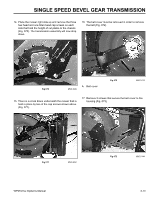
6.
Coat the axle, key, and spring with #2 molybendum
disulfide grease or anti-seize compound before
installing the pinion (Fig. 087).
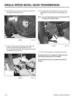
7.
The wheel pinion is marked with an R and L for right
and left. Identify right and left from the operator’s
position (Fig. 088). On the right side, the R should
face outward. The letter L should face outward on
the left side. If the wheel pinions are reversed, the
wheels will not drive.
Fig 088
MVC-474
R
Note: See Chapter 5 for more information on Wheel
Clutches.