Toshiba Tecra R850 User Manual - Page 46
Battery lock, Docking port, Battery release latch, TOSHIBA Hi-Speed Port Replicator II described
 |
View all Toshiba Tecra R850 manuals
Add to My Manuals
Save this manual to your list of manuals |
Page 46 highlights
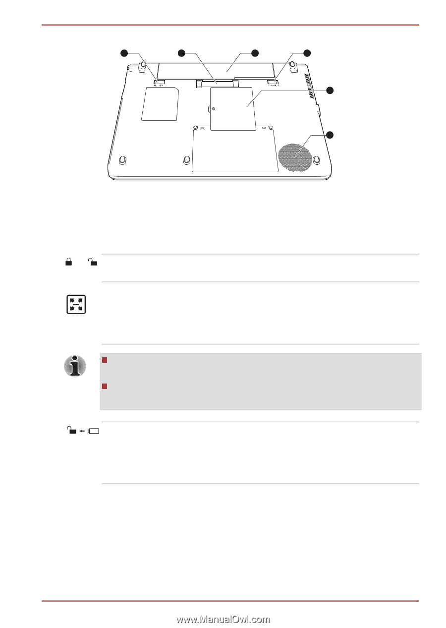
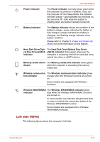
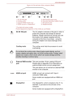
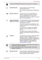
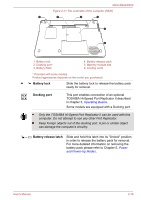
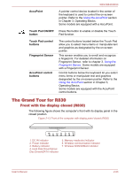
R850/R840/R830 Figure 2-11 The underside of the computer (R840) 1 2 3 4 5 6 1. Battery lock 2. Docking port* 3. Battery Pack 4. Battery release latch 5. Memory module slot 6. Cooling vents * Provided with some models. Product appearance depends on the model you purchased. Battery lock Slide the battery lock to release the battery pack ready for removal. Docking port This port enables connection of an optional TOSHIBA Hi-Speed Port Replicator II described in chapter 3, Operating Basics. Some models are equipped with a Docking port. Only the TOSHIBA Hi-Speed Port Replicator II can be used with this computer. Do not attempt to use any other Port Replicator. Keep foreign objects out of the docking port. A pin or similar object can damage the computer's circuitry. Battery release latch Slide and hold this latch into its "Unlock" position in order to release the battery pack for removal. For more detailed information on removing the battery pack please refer to Chapter 5, Power and Power-Up Modes. User's Manual 2-18
-
 1
1 -
2
-
3
-
4
-
5
-
6
-
7
-
8
-
9
-
10
-
11
-
12
-
13
-
14
-
15
-
16
-
17
-
18
-
19
-
20
-
21
-
22
-
23
-
24
-
25
-
26
-
27
-
28
-
29
-
30
-
31
-
32
-
33
-
34
-
35
-
36
-
37
-
38
-
39
-
40
-
 41
41 -
 42
42 -
 43
43 -
 44
44 -
 45
45 -
 46
46 -
 47
47 -
 48
48 -
 49
49 -
 50
50 -
 51
51 -
52
-
53
-
54
-
55
-
56
-
57
-
58
-
59
-
60
-
61
-
62
-
63
-
64
-
65
-
66
-
67
-
68
-
69
-
70
-
71
-
72
-
73
-
74
-
75
-
76
-
77
-
78
-
79
-
80
-
81
-
82
-
83
-
84
-
85
-
86
-
87
-
88
-
89
-
90
-
91
-
92
-
93
-
94
-
95
-
96
-
97
-
98
-
99
-
100
-
101
-
102
-
103
-
104
-
105
-
106
-
107
-
108
-
109
-
110
-
111
-
112
-
113
-
114
-
115
-
116
-
117
-
118
-
119
-
120
-
121
-
122
-
123
-
124
-
125
-
126
-
127
-
128
-
129
-
130
-
131
-
132
-
133
-
134
-
135
-
136
-
137
-
138
-
139
-
140
-
141
-
142
-
143
-
144
-
145
-
146
-
147
-
148
-
149
-
150
-
151
-
152
-
153
-
154
-
155
-
156
-
157
-
158
-
159
-
160
-
161
-
162
-
163
-
164
-
165
-
166
-
167
-
168
-
169
-
170
-
171
-
172
-
173
-
174
-
175
-
176
-
177
-
178
-
179
-
180
-
181
-
182
-
183
-
184
-
185
-
186
-
187
-
188
-
189
-
190
-
191
-
192
-
193
-
194
-
195
-
196
-
197
-
198
-
199
-
200
-
201
-
202
-
203
-
204
-
205
-
206
-
207
-
208
 |
 |