Alesis iO Mix Reference Manual - Page 14
Rear Panel
 |
View all Alesis iO Mix manuals
Add to My Manuals
Save this manual to your list of manuals |
Page 14 highlights
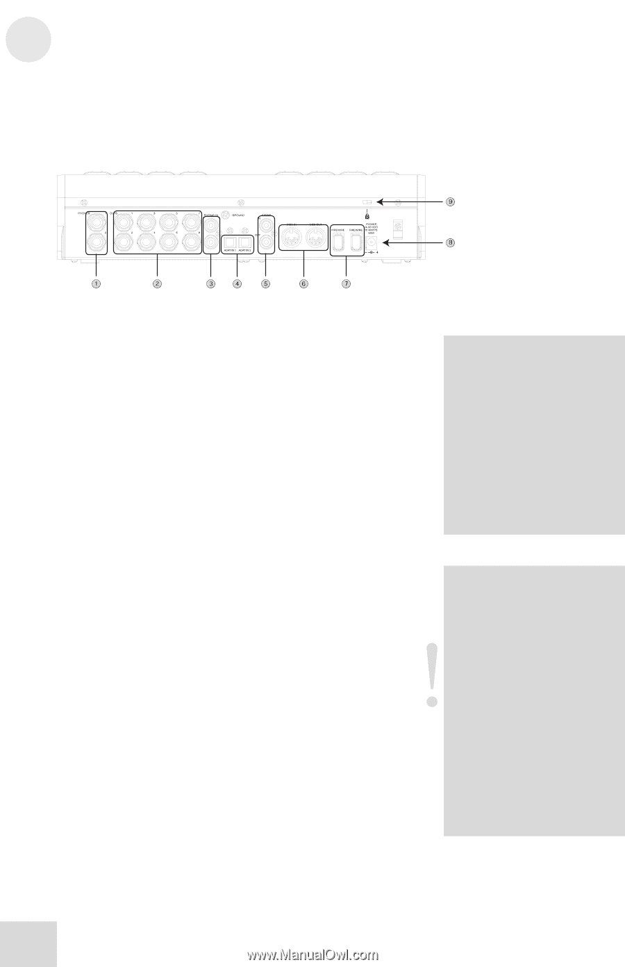
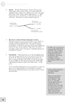
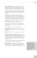
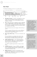
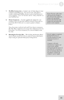
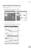
1 Hardware Overview Rear Panel You'll find the following on the rear of your IO|14/26: 1. Headphone Outputs - Connect your headphones to these outputs. The first headphone output always mirrors the analog 1/2 output pair. The second headphone output is assignable in software. 2. Main outputs (8 outputs on IO|26; 2 outputs on IO|14) - Use ¼," "TRS" cables to connect these outputs to the balanced inputs of your powered speakers or power amplifier. If your speakers or amplifier only provide unbalanced inputs, use unbalanced ("TS") cables. The IO|26 (shown above) has 8 outputs. The IO|14 has 2 outputs. If you are using the IO|26 and wish to connect additional speakers, headphone amplifiers or hardware processors, connect them to outputs 3 through 8. 3. Phono input (IO|26 only) - Connect your turntable to this input. If your turntable has a grounding cable, attach it to the grounding screw to the upper right of the phono inputs. This grounding will minimize humming and buzzing. 4. ADAT Lightpipe Inputs - These optical digital inputs can accommodate a wide variety of ADAT-enabled gear. The IO|14 has one ADAT input whereas the IO|26 (shown above) has two ADAT inputs. Use ADAT-compatible optical cables to connect to these inputs. 5. S/PDIF Connectors - Connect S/PDIF-enabled digital devices (such as the Alesis Masterlink, CD players, DAT machines, MiniDisc Recorders, etc.) to your IO|14/26 using coaxial, RCA-terminated cables. 6. MIDI Connectors - Connect your keyboards, sound modules, or other MIDI devices to your IO|14/26 using 5pin MIDI cables. Remember to chain the OUTs of each device to the INs of other devices. The IO14/26's outputs are "impedance balanced." This wiring method provides all of the benefits of "fully balanced" wiring when the outputs are connected to balanced gear. Furthermore, impedance balancing, unlike other balancing methods, allows for trouble-free connection to unbalanced devices. If you connect an ADAT or S/PDIF input device (or both), you will need to select one of them as the "clock master" in the IO's control panel. The device you select as the clock master will determine the IO's clock rate and will be responsible for keeping all of the digital signals synchronized. Therefore, if you turn this device off, you will need to select another clok master in the control panel. 12
-
 1
1 -
2
-
3
-
4
-
5
-
6
-
7
-
8
-
 9
9 -
 10
10 -
 11
11 -
 12
12 -
 13
13 -
 14
14 -
 15
15 -
 16
16 -
 17
17 -
 18
18 -
 19
19 -
20
-
21
-
22
-
23
-
24
-
25
-
26
-
27
-
28
-
29
-
30
-
31
-
32
-
33
-
34
-
35
-
36
-
37
-
38
-
39
-
40
-
41
-
42
-
43
-
44
-
45
-
46
-
47
-
48
-
49
-
50
-
51
-
52
-
53
-
54
-
55
-
56
-
57
-
58
-
59
-
60
-
61
-
62
-
63
-
64
-
65
-
66
-
67
-
68
-
69
-
70
 |
 |