Alpine 1004 Owners Manual - Page 51
Left Front - Speaker Output Lead White/Black - accessories
 |
View all Alpine 1004 manuals
Add to My Manuals
Save this manual to your list of manuals |
Page 51 highlights
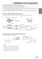
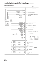
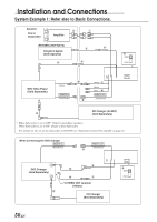
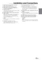
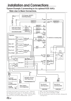
Installation and Connections 1 Remote Control Interface Connector Connect to the remote control interface box. 2 Remote Control Output Lead (White/Brown) Connect this lead to the remote control input lead. This lead outputs the controlling signals from the remote control. 3 Foot Brake Lead Connect to the vehicle's foot brake lead or brake lamp lead. 4 RGB input Connector 5 Ai-NET Cable 6 Power Supply Connector 7 System Switch When connecting an equalizer or divider using AiNET feature, place this switch in the EQ/DIV position. When no device is connected, leave the switch in the NORM position. NOTE Be sure turn the power off to the unit before changing the switch position. 8 Illumination Lead (Orange) This lead may be connected to the vehicle's instrument cluster illumination lead. This will allow the backlighting of the CVA-1004 to dim whenever the vehicle's lights are turned on. 9 Remote Turn-On Lead (Blue/White) Connect this lead to the remote turn-on lead of your amplifier or signal processor. ! Power Antenna Lead (Blue) Connect this lead to the +B terminal of your power antenna, if applicable. " Audio Interrupt In Lead (Pink/Black) # Parking Brake Lead (Yellow/Blue) Connect this lead to the power supply side of the parking brake switch to transmit the parking brake status signals to the CVA-1004. $ Switched Power Lead (Ignition) (Red) Connect this lead to an open terminal on the vehicle's fuse box or another unused power source which provides (+) 12V only when the ignition is turned on or in the accessory position. % Battery Lead (Yellow) Connect this lead to the positive (+) post of the vehicle's battery. & Fuse Holder (10A) ( Ground Lead (Black) Connect this lead to a good chassis ground on the vehicle. Make sure the connection is made to bare metal and is securely fastened using the sheet metal screw provided. ) Right Front (+) Speaker Output Lead (Gray) ~ Right Front (-) Speaker Output Lead (Gray/ Black) + Right Rear (-) Speaker Output Lead (Violet/ Black) , Right Rear (+) Speaker Output Lead (Violet) - Left Rear (+) Speaker Output Lead (Green) . Left Rear (-) Speaker Output Lead (Green/ Black) / Left Front (-) Speaker Output Lead (White/Black) : Left Front (+) Speaker Output Lead (White) ; Antenna Receptacle 49-EN
-
 1
1 -
2
-
3
-
4
-
5
-
6
-
7
-
8
-
9
-
10
-
11
-
12
-
13
-
14
-
15
-
16
-
17
-
18
-
19
-
20
-
21
-
22
-
23
-
24
-
25
-
26
-
27
-
28
-
29
-
30
-
31
-
32
-
33
-
34
-
35
-
36
-
37
-
38
-
39
-
40
-
41
-
42
-
43
-
44
-
45
-
 46
46 -
 47
47 -
 48
48 -
 49
49 -
 50
50 -
 51
51 -
 52
52 -
 53
53 -
 54
54 -
 55
55 -
 56
56 -
57
 |
 |
