Alpine 1004 Owners Manual - Page 54
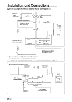
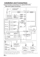
System Example 2 connecting to the optional KCE-104V, Refer also to Basic Connections.
 |
View all Alpine 1004 manuals
Add to My Manuals
Save this manual to your list of manuals |
Page 54 highlights
Installation and Connections System Example 2 (connecting to the optional KCE-104V): Refer also to Basic Connections. CD Changer (Ai-NET) (Sold Separately) 4 3 REMOTE IN (White/Brown) DVD Video Player (Sold Separately) (DVA-5205/DHA-S680) (Yellow) ) (White: L-ch) (Red: R-ch) ~ Speakers ~ Subwoofers Amplifier Rear Left ~ Amplifier Rear Right Front Left ~ Amplifier Front Right REAR SEL 1 5 (Grey/Pink) REAR SEL 2 6 (Black/Pink) IGNITION 7 (Red) REVERSE 8 " (Orange/White) BATTERY 9 (Yellow) GND ! (Black) + A N B C M L + E (KCE-104V)∗1 K J D F I G H [ ] \ 1 2 REMOTE OUT (White/Brown) To vehicle's reversing lamp % (Red) & (White) (Yellow) ( $# ∗3 NORM EQ/DIV ^ KCE-150V (Sold Separately) TV Tuner (Sold Separately) COLOR ON ∗2 CONTROL OFF Navigation System ~ (Sold Separately) (NVE-N852A/NVE-871A) Rear Camera (Sold Separately) For details of each setting of external devices, refer to "Setting the External Expansion Box" (page 35), "Rear Monitor Setting" (page 36), "Setting the External Input" (page 37) and "Setting Front/Rear/ Subwoofer Preout of the External Expansion Box" (page 37). 52-EN ~ ~ Rear Monitor (Sold Separately) Rear Monitor (Sold Separately) (TME-M760) (TME-M760) *1 Refer to the KCE-104V detail on page 53. *2 Set the color control of TV Tuner to OFF. *3 Be sure turn the power off to the unit before changing the switch position.
-
 1
1 -
2
-
3
-
4
-
5
-
6
-
7
-
8
-
9
-
10
-
11
-
12
-
13
-
14
-
15
-
16
-
17
-
18
-
19
-
20
-
21
-
22
-
23
-
24
-
25
-
26
-
27
-
28
-
29
-
30
-
31
-
32
-
33
-
34
-
35
-
36
-
37
-
38
-
39
-
40
-
41
-
42
-
43
-
44
-
45
-
46
-
47
-
48
-
 49
49 -
 50
50 -
 51
51 -
 52
52 -
 53
53 -
 54
54 -
 55
55 -
 56
56 -
 57
57
 |
 |
