Alpine 1004 Owners Manual - Page 55
Detail of the expansion box KCE-104V sold separately - cva cd box
 |
View all Alpine 1004 manuals
Add to My Manuals
Save this manual to your list of manuals |
Page 55 highlights
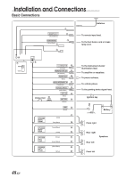
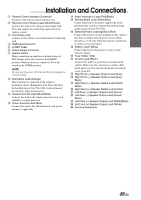
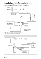
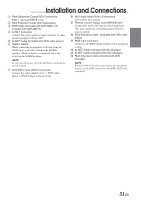
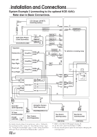
Installation and Connections Detail of the expansion box KCE-104V (sold separately) A N B C D E F G (Red) (Yellow) < (White) (Red) < (Yellow) (White) > (Red) ? ; (White) (Yellow) = (White) (Red) @ (White) , (Red) (White) / (Yellow) (Red) , (White) - (Red) (Red) (White) (Red) . (White) (Yellow) (Red) : (White) (Yellow) M L K J I H 1 Ai-NET Connector Connect this to the output or input connector of other product equipped with Ai-NET. 2 Remote Control Output Lead (White/Brown) Connect this lead to the remote control input lead. This lead outputs the controlling signals from the remote control. 3 Ai-NET Cable (Included with DVD video player) 4 Ai-NET Cable (Included with CD Changer) 5 Rear Select 1 Lead (Grey/Pink) Connect this lead to the ground with a push switch, etc. 6 Rear Select 2 Lead (Black/Pink) Connect this lead to the ground with a push switch, etc. 7 Switched Power Lead (Ignition) (Red) Connect this lead to an open terminal on the vehicle's fuse box or another unused power source which provides (+) 12V only when the ignition is turned on or in the accessory position. 8 Reverse Lamp Signal Input Lead (Orange/White) Used to automatically switch to the rear camera input. Connect this lead to the positive side of the vehicle's reverse lamp. The video input will automatically switch to the rear camera whenever the vehicle is backing up. 9 Battery Lead (Yellow) Connect this lead to the positive (+) post of the vehicle's battery. ! Ground Lead (Black) Connect this lead to a good chassis ground on the vehicle. Make sure the connection is made to bare metal and is securely fastened using the sheet metal screw provided. " Fuse Holder (7.5A) # System Switch When connecting an equalizer or divider using Ai-NET feature, place this switch in the EQ/DIV position. When no device is connected, leave the switch in the NORM position. $ RGB Input Connector Connect to the RGB output terminal of the KCE-104V. % Rear/Subwoofer Output RCA Connectors RED is right and WHITE is left. & AUX Audio Input (AUX1) Connectors ( AUX Video Input (AUX1) Connector ) RCA Extension Cable (Included with DVD video player) ~ RCA Extension Cable (Sold Separately) + RCA Extension Cable (Included with KCE-104V) , To Front/Rear PREOUT Terminals of the KCE-104V - To Subwoofer Terminals of the KCE-104V . Connect to the AUX Input (AUX1) Connectors of the CVA-1004 / To AUX1 Output Terminals of the KCE-104V : To AUX2 Output Terminals of the KCE-104V ; To Sound Input Terminals of the KCE-104V (from the CVA-1004) < To AUX Input1 Terminals of the KCE-104V = To AUX Input2 Terminals of the KCE-104V > To AUX Input3 Terminals of the KCE-104V ? Connect to the RGB Terminal of the Navigation System @ Connect to the RGB Input Terminal of the CVA-1004 [ RGB Cable (Included with KCE-104V) \ RGB Cable (Included with NVE-N852, not included with NVE-N871A) ] RCA Extension Cable (Included with KCE-150V) ^ To Video Output Terminals 53-EN
-
 1
1 -
2
-
3
-
4
-
5
-
6
-
7
-
8
-
9
-
10
-
11
-
12
-
13
-
14
-
15
-
16
-
17
-
18
-
19
-
20
-
21
-
22
-
23
-
24
-
25
-
26
-
27
-
28
-
29
-
30
-
31
-
32
-
33
-
34
-
35
-
36
-
37
-
38
-
39
-
40
-
41
-
42
-
43
-
44
-
45
-
46
-
47
-
48
-
49
-
 50
50 -
 51
51 -
 52
52 -
 53
53 -
 54
54 -
 55
55 -
 56
56 -
 57
57
 |
 |
