Alpine iLX-507 Owners Manual - Page 80
Installation example using the Original Mounting Bracket
 |
View all Alpine iLX-507 manuals
Add to My Manuals
Save this manual to your list of manuals |
Page 80 highlights
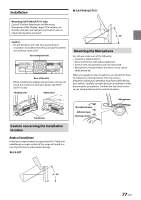
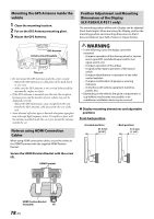
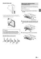
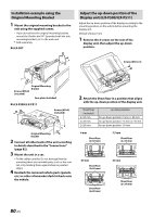
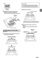
Installation example using the Original Mounting Bracket 1 Mount the original mounting bracket to the unit using the supplied screws. • If you do not have the original mounting bracket, mount the Double din KIT* (provided with the side mounting bracket), etc. to the main unit. * Sold separately. ■ iLX-507 Adjust the up-down position of the Display unit (iLX-F509/iLX-F511) Adjust the up-down position of the display according to the mounting position on the vehicle before mounting the display unit. Default setting: 0 mm 1 Remove the 4 screws on the rear of the display unit, then adjust the up-down position. Screws (M2.6× 8) Original Mounting Bracket Screws (M5×8) (included) Face plate (Included) ■ iLX-F509/iLX-F511 Screws (M5×8) (included) Original Mounting Bracket 2 Connect all other leads of the unit according to details described in the "Connections" (page 82). 3 Mount the unit in a car. • Fix the cables carefully. Do not damage them by mounting them into movable parts, such as the seat rail, or by locating them against sharp or pointed edges. 4 Reattach the removed vehicle parts (panels, etc.) or other aftermarket dash kit back onto the vehicle. 2 Attach the Sheet Rear in a position that aligns with the up-down position of the display unit. Sheet Rear (Included) 2×50 mm: 2×35 mm: 2×20 mm: up-down position for up-down position 0 mm or -60 mm for up-down position -15 mm or -45 mm for up-down position -30 mm 0 mm Sheet Rear (2×50 mm) -15 mm Sheet Rear (2×35 mm) -30 mm Sheet Rear (2×20 mm) Sheet Rear (2×20 mm) -45 mm Sheet Rear (2×35 mm) 80-EN
-
 1
1 -
2
-
3
-
4
-
5
-
6
-
7
-
8
-
9
-
10
-
11
-
12
-
13
-
14
-
15
-
16
-
17
-
18
-
19
-
20
-
21
-
22
-
23
-
24
-
25
-
26
-
27
-
28
-
29
-
30
-
31
-
32
-
33
-
34
-
35
-
36
-
37
-
38
-
39
-
40
-
41
-
42
-
43
-
44
-
45
-
46
-
47
-
48
-
49
-
50
-
51
-
52
-
53
-
54
-
55
-
56
-
57
-
58
-
59
-
60
-
61
-
62
-
63
-
64
-
65
-
66
-
67
-
68
-
69
-
70
-
71
-
72
-
73
-
74
-
 75
75 -
 76
76 -
 77
77 -
 78
78 -
 79
79 -
 80
80 -
 81
81 -
 82
82 -
 83
83 -
 84
84 -
 85
85 -
86
-
87
-
88
-
89
-
90
-
91
-
92
 |
 |
