Brother International BES-116 Instruction Manual - English - Page 144
Electrical
 |
View all Brother International BES-116 manuals
Add to My Manuals
Save this manual to your list of manuals |
Page 144 highlights
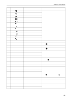
Chapter 10 Troubleshooting Electrical Section Cautions • Be sure to turn off the power of the machine and unplug the power cord before checking cable connections. • When you check connection of the cables as instructed in this manual, also check connection and continuity between connectors. • Carry out items described in the "Measures" section in order of appearance. • Some checks and replacement works can be conducted only by repair people. In such cases, contact your dealer. Symptom Measures The machine does not operate even if the power is turned on. • Is the power cord of the machine plugged in? Plug in the power cord. • Is the connector in the control box connected? Connect it after checking the types and colors of the connectors. • Is fuse F1 or F5 on the power PCB in the control box blown? Replace the fuse with a new one. If the fuse is blown again, something is faulty. Check to see if the wiring is correct. Replace the control box with a new one. The machine does not operate even if the power is turned on. The message, "Release stop SW to operate!", is displayed on the panel. • Is the stop switch (Option) turned on? Reset the stop switch. An overtravel error occurs. • Is the frame within the cap frame area? Move the frame within the cap frame area and turn on the power. • Check to see if the signal of the X area sensor turns ON and OFF in PORT test mode. When the signal does not change, refer to the block diagram showing the cable connections and check to see if connection from the X cap sensor to the main PCB is proper. Replace the X cap sensor with a new one. The needle stop position error occurs. • Is the pulley manually turned and out of the stop angle? Turn the pulley, adjust the needle at the stop position, and reset the error. • Check the signal of the stop position sensor in the encoder test mode. Refer to the adjustment or cable connection block diagram and check connection from the needle position detention sensor to the main PCB. Replace the needle position detection sensor with a new one. • Is the main shaft brake solenoid operating? If not, refer to the block diagram showing the cable connections and check to see if the connections from the brake solenoid to the power PCB and from connector P27 of the power PCB to connector P1 of the main PCB are proper. 142 BES-116AC
-
 1
1 -
2
-
3
-
4
-
5
-
6
-
7
-
8
-
9
-
10
-
11
-
12
-
13
-
14
-
15
-
16
-
17
-
18
-
19
-
20
-
21
-
22
-
23
-
24
-
25
-
26
-
27
-
28
-
29
-
30
-
31
-
32
-
33
-
34
-
35
-
36
-
37
-
38
-
39
-
40
-
41
-
42
-
43
-
44
-
45
-
46
-
47
-
48
-
49
-
50
-
51
-
52
-
53
-
54
-
55
-
56
-
57
-
58
-
59
-
60
-
61
-
62
-
63
-
64
-
65
-
66
-
67
-
68
-
69
-
70
-
71
-
72
-
73
-
74
-
75
-
76
-
77
-
78
-
79
-
80
-
81
-
82
-
83
-
84
-
85
-
86
-
87
-
88
-
89
-
90
-
91
-
92
-
93
-
94
-
95
-
96
-
97
-
98
-
99
-
100
-
101
-
102
-
103
-
104
-
105
-
106
-
107
-
108
-
109
-
110
-
111
-
112
-
113
-
114
-
115
-
116
-
117
-
118
-
119
-
120
-
121
-
122
-
123
-
124
-
125
-
126
-
127
-
128
-
129
-
130
-
131
-
132
-
133
-
134
-
135
-
136
-
137
-
138
-
 139
139 -
 140
140 -
 141
141 -
 142
142 -
 143
143 -
 144
144 -
 145
145 -
 146
146 -
 147
147 -
 148
148 -
 149
149 -
150
-
151
-
152
-
153
 |
 |