Brother International BES-116 Instruction Manual - English - Page 145
Symptom, Measures, to the main PCB is proper.
 |
View all Brother International BES-116 manuals
Add to My Manuals
Save this manual to your list of manuals |
Page 145 highlights
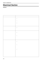
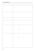
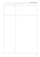
Chapter 10 Troubleshooting Symptom Measures X-axis or Y-axis home position detection error occurs. • Was the XY carriage moving? If so, refer to the block diagram showing the cable connections and check to see if connection from the X and Y area sensor to the main PCB is proper. • Was the XY motor rotating? If so, check the XY carriage mechanism. • If the XY motor is not rotating, refer to the cable connection block diagram and check to see if connection from the XY motor to the main PCB is proper. The thread breakage error frequently occurs although thread is not broken. • Enter the needle bar case test mode by pressing and STOP the thread breakage pulley. , turn If the needle bar number icon is displayed reversely, lower the thread breakage sensitivity value of the machine controller. (The standard value is 0.) • Check connection from the thread breakage sensor PCB to the head PCB if the needle bar number icon is not displayed reversely. • Replace the thread breakage sensor PCB with a new one. The main shaft motor lock error occurs. • Enter the encoder signal mode and manually turn the main shaft pulley. If it is abnormally heavy, the main shaft mechanism is faulty. • Does the main shaft motor rotate at all when the error occurs? If it does not rotate at all, check fuse F1 and F5 on the power supply PCB in the control box. Refer to the block diagram showing the cable connections and check to see if connection from the main shaft motor to the main PCB is proper. Also check connection of connectors P15 and P16 of the main PCB and connectors P1 and P2 on the power PCB in the box, and connection from connector P14 of the main PCB to the 14v terminal of the power transformer. • Manually turn the main shaft pulley in the encoder signal test mode and check to see if the stop position signal and encoder signal are proper. If either of the signals does not change, refer to the block diagram showing the cable connections and check to see if connection from the encoder and stop position sensor to the main PCB is proper. ERROR A8 frequently occurs. • In the encoder signal test mode, manually turn the main shaft pulley and check to see that the stop position signal is correct. If the signal does not change, refer to the cable connection block diagram and check to see if connection from the stop position sensor to the main PCB is proper. BES-116AC 143
-
 1
1 -
2
-
3
-
4
-
5
-
6
-
7
-
8
-
9
-
10
-
11
-
12
-
13
-
14
-
15
-
16
-
17
-
18
-
19
-
20
-
21
-
22
-
23
-
24
-
25
-
26
-
27
-
28
-
29
-
30
-
31
-
32
-
33
-
34
-
35
-
36
-
37
-
38
-
39
-
40
-
41
-
42
-
43
-
44
-
45
-
46
-
47
-
48
-
49
-
50
-
51
-
52
-
53
-
54
-
55
-
56
-
57
-
58
-
59
-
60
-
61
-
62
-
63
-
64
-
65
-
66
-
67
-
68
-
69
-
70
-
71
-
72
-
73
-
74
-
75
-
76
-
77
-
78
-
79
-
80
-
81
-
82
-
83
-
84
-
85
-
86
-
87
-
88
-
89
-
90
-
91
-
92
-
93
-
94
-
95
-
96
-
97
-
98
-
99
-
100
-
101
-
102
-
103
-
104
-
105
-
106
-
107
-
108
-
109
-
110
-
111
-
112
-
113
-
114
-
115
-
116
-
117
-
118
-
119
-
120
-
121
-
122
-
123
-
124
-
125
-
126
-
127
-
128
-
129
-
130
-
131
-
132
-
133
-
134
-
135
-
136
-
137
-
138
-
139
-
 140
140 -
 141
141 -
 142
142 -
 143
143 -
 144
144 -
 145
145 -
 146
146 -
 147
147 -
 148
148 -
 149
149 -
 150
150 -
151
-
152
-
153
 |
 |