Brother International BES-116 Instruction Manual - English - Page 146
ERROR E5 to ERROR FF frequently, operate with the connector
 |
View all Brother International BES-116 manuals
Add to My Manuals
Save this manual to your list of manuals |
Page 146 highlights
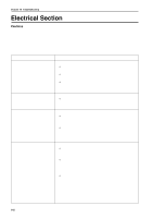
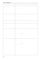
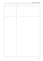
Chapter 10 Troubleshooting Symptom Measures Main shaft rotation speed error occurs. • Enter the encoder signal test mode and manually turn the main shaft pulley. If it is abnormally heavy, the main shaft mechanism is faulty. • Refer to the block diagram showing the cable connections and check to see if connection from the main shaft motor to the main PCB is proper. Also check the connection from connectors P14 of the main PCB to the 14v terminal of the power transformer. Exhaust fan motor stops. • Refer to the block diagram showing the cable connections and check to see if connection of connector P22 of the main PCB in the control box is proper. • Check fuse F3 on the power supply PCB. If it is blown, replace it with a new one. If it becomes blown again, the 24v system circuit is faulty. ERROR E5 to ERROR FF frequently • Replace the main PCB with a new one. occur. All solenoids of head do not operate. • Refer to the block diagram showing cable connections and check fuse F2 on the power supply PCB. If it is blown, replace it with a new one. The 60v circuit is faulty if the fuse is blown immediately after turning on the power even after replacing the fuse. Jump solenoid does not operate. Pickker solenoid does not operate. • Check to see if connection from the jump solenoid to connector P10 of the head PCB is proper. • Check the resistance value of the jump solenoid which does not operate with the connector section. The normal resistance value is approximately 185Ω. If it is faulty, replace the solenoid with a new one. In this case, the head PCB may also be faulty. Also replace the head PCB with a new one if it does not operate properly even after replacing the solenoid. • Replace the head PCB with a new one. • Check to see if connection from the pickker solenoid to connector P8 of the head PCB is proper. • Check the resistance value of the pickker solenoid which does not operate with the connector section. The normal resistance value is approximately 426Ω. If it is faulty, replace the solenoid with a new one. In this case, the head PCB may also be faulty. Also replace the head PCB with a new one if it does not operate properly even after replacing the solenoid. • Replace the head PCB with a new one. 144 BES-116AC
-
 1
1 -
2
-
3
-
4
-
5
-
6
-
7
-
8
-
9
-
10
-
11
-
12
-
13
-
14
-
15
-
16
-
17
-
18
-
19
-
20
-
21
-
22
-
23
-
24
-
25
-
26
-
27
-
28
-
29
-
30
-
31
-
32
-
33
-
34
-
35
-
36
-
37
-
38
-
39
-
40
-
41
-
42
-
43
-
44
-
45
-
46
-
47
-
48
-
49
-
50
-
51
-
52
-
53
-
54
-
55
-
56
-
57
-
58
-
59
-
60
-
61
-
62
-
63
-
64
-
65
-
66
-
67
-
68
-
69
-
70
-
71
-
72
-
73
-
74
-
75
-
76
-
77
-
78
-
79
-
80
-
81
-
82
-
83
-
84
-
85
-
86
-
87
-
88
-
89
-
90
-
91
-
92
-
93
-
94
-
95
-
96
-
97
-
98
-
99
-
100
-
101
-
102
-
103
-
104
-
105
-
106
-
107
-
108
-
109
-
110
-
111
-
112
-
113
-
114
-
115
-
116
-
117
-
118
-
119
-
120
-
121
-
122
-
123
-
124
-
125
-
126
-
127
-
128
-
129
-
130
-
131
-
132
-
133
-
134
-
135
-
136
-
137
-
138
-
139
-
140
-
 141
141 -
 142
142 -
 143
143 -
 144
144 -
 145
145 -
 146
146 -
 147
147 -
 148
148 -
 149
149 -
 150
150 -
 151
151 -
152
-
153
 |
 |
