Brother International HL-6050DN Users Manual - English - Page 107
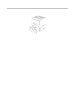
Put the side cover back on., Plug the printer back in, and then turn on the power switch.
 |
UPC - 012502609568
View all Brother International HL-6050DN manuals
Add to My Manuals
Save this manual to your list of manuals |
Page 107 highlights
4 Loosen the two screws, and then remove the Network cover plate. Figure 4-10 5 Put the NC-7100w print server connector firmly into the connector of the main controller board by aligning the two screws to the groove of the printer, and then secure it with the two screws. 6 Close the interface access cover. 7 Put the side cover back on. Figure 4-11 8 Plug the printer back in, and then turn on the power switch. 4 - 7 OPTIONS
-
 1
1 -
2
-
3
-
4
-
5
-
6
-
7
-
8
-
9
-
10
-
11
-
12
-
13
-
14
-
15
-
16
-
17
-
18
-
19
-
20
-
21
-
22
-
23
-
24
-
25
-
26
-
27
-
28
-
29
-
30
-
31
-
32
-
33
-
34
-
35
-
36
-
37
-
38
-
39
-
40
-
41
-
42
-
43
-
44
-
45
-
46
-
47
-
48
-
49
-
50
-
51
-
52
-
53
-
54
-
55
-
56
-
57
-
58
-
59
-
60
-
61
-
62
-
63
-
64
-
65
-
66
-
67
-
68
-
69
-
70
-
71
-
72
-
73
-
74
-
75
-
76
-
77
-
78
-
79
-
80
-
81
-
82
-
83
-
84
-
85
-
86
-
87
-
88
-
89
-
90
-
91
-
92
-
93
-
94
-
95
-
96
-
97
-
98
-
99
-
100
-
101
-
 102
102 -
 103
103 -
 104
104 -
 105
105 -
 106
106 -
 107
107 -
 108
108 -
 109
109 -
 110
110 -
 111
111 -
 112
112 -
113
-
114
-
115
-
116
-
117
-
118
-
119
-
120
-
121
-
122
-
123
-
124
-
125
-
126
-
127
-
128
-
129
-
130
-
131
-
132
-
133
-
134
-
135
-
136
-
137
-
138
-
139
-
140
-
141
-
142
-
143
-
144
-
145
-
146
-
147
-
148
-
149
-
150
-
151
-
152
-
153
-
154
-
155
-
156
-
157
-
158
-
159
-
160
-
161
-
162
-
163
-
164
-
165
-
166
-
167
-
168
-
169
-
170
-
171
-
172
-
173
-
174
-
175
-
176
-
177
-
178
-
179
 |
 |
4 - 7
OPTIONS
4
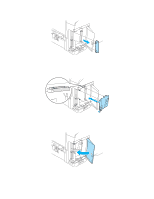
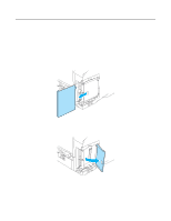
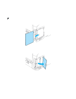
Loosen the two screws, and then remove the Network cover plate.
Figure 4-10
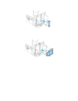
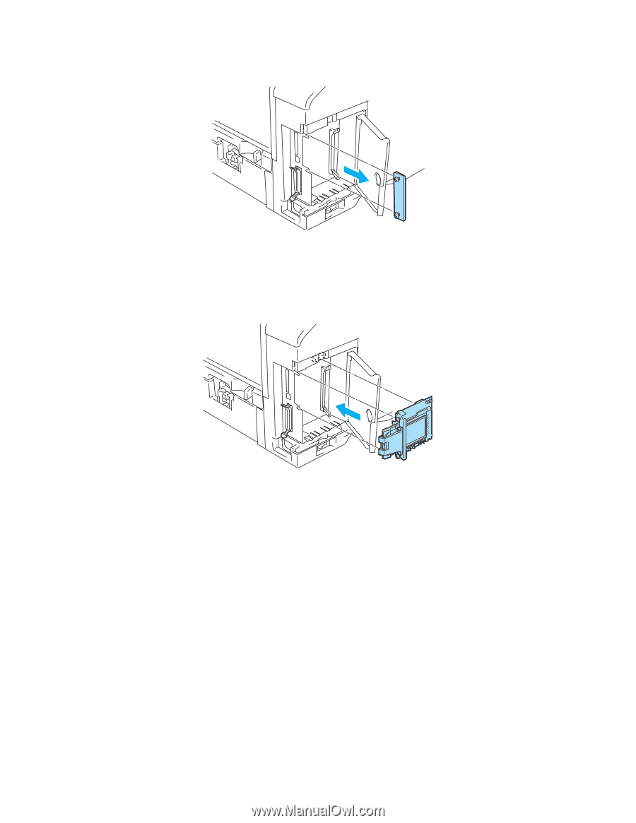
5
Put the NC-7100w print server connector firmly into the connector of the main controller board by
aligning the two screws to the groove of the printer, and then secure it with the two screws.
Figure 4-11
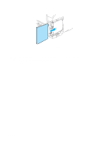
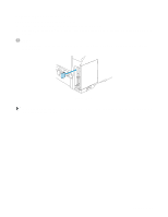
6
Close the interface access cover.
7
Put the side cover back on.
8
Plug the printer back in, and then turn on the power switch.