| Section |
Page |
| Front Cover |
1 |
| Year 2000 Compliant |
2 |
| Brother Numbers |
3 |
| Fax-Back System |
3 |
| Brother on the World Wide Web |
3 |
| Brother Bulletin Board |
3 |
| For Customer Service |
3 |
| Ordering Accessories and Supplies |
4 |
| Table of Contents |
5 |
| Chapter 1 Introduction |
15 |
| Using This Manual |
15 |
| Finding Information |
15 |
| Test Sheet Procedures (For USA Only) |
16 |
| About Fax Machines |
16 |
| Fax Tones and Handshake |
16 |
| ECM (Error Correction Mode) |
17 |
| MFC 4350, MFC 4650 and MFC 7750 Control Panel Overview |
18 |
| MFC 4350, MFC 4650 and MFC 7750 Control Panel Keys |
19 |
| MFC 6650MC Control Panel Overview |
20 |
| MFC 6650MC Control Panel Keys |
21 |
| Chapter 2 MFC Setup and Connections |
23 |
| Caution |
23 |
| Packing List |
24 |
| Choosing a Location |
25 |
| Assembly |
26 |
| Installingl the Drum Unit Assembly (with Toner Cartridge) |
26 |
| Setting Up the MFC |
28 |
| Loading Paper in Multi-Purpose Sheet Feeder |
30 |
| Attaching Dust Cover |
31 |
| Manual Feed Slot |
32 |
| Acceptable Paper |
32 |
| Loading one sheet of paper |
32 |
| Paper Capacity in Feeder |
33 |
| Connecting an External Telephone Answering Device (TAD) |
33 |
| Sequence |
33 |
| Connections |
34 |
| Recording Outgoing Message (OGM) |
35 |
| Connecting an External Telephone |
35 |
| Special Line Considerations |
36 |
| Roll Over Phone Lines |
36 |
| Two-Line Phone System |
36 |
| Converting Telephone Wall Outlets |
36 |
| Installing MFC, External Two-Line TAD, and Two-Line Telephone |
37 |
| Multi-Line Connections (PBX) |
38 |
| Custom Features on a Single Line |
38 |
| Chapter 3 On-Screen Programming |
39 |
| User-Friendly Programming |
39 |
| Function Mode |
39 |
| Alternating Displays |
40 |
| Function Selection Table |
41 |
| Chapter 4 Initial Setup |
45 |
| Getting Started |
45 |
| Setting Dialing Mode (Tone/Pulse) |
45 |
| Setting Date and Time |
46 |
| Setting Station ID |
47 |
| Entering Text |
48 |
| Setting Beeper Volume |
50 |
| Setting the Handset Volume |
50 |
| Setting the Speaker Volume |
50 |
| Setting the Ring Volume |
51 |
| Memory Storage |
51 |
| Sleep Mode |
51 |
| Delayed Timer |
52 |
| Chapter 5 Setup Receive |
53 |
| Basic Receiving Operations |
53 |
| Select Answer Mode |
53 |
| Setting Ring Delay |
54 |
| Setting F/T Ring Time |
55 |
| Record FAX/TEL Outgoing Announcement (F/T OGM) (For MFC 6650MC Only) |
55 |
| Easy Receive |
56 |
| Printing a Reduced Incoming Document |
56 |
| Recommended Reductions |
57 |
| Setting Paper Size |
57 |
| Setting the Print Density |
58 |
| Toner Save |
58 |
| Advanced Receiving Operations |
58 |
| Operation from Extension Telephone (For MFC 4350, MFC 4650 and MFC 6650MC only) or External Telephone |
58 |
| For FAX/TEL Mode Only |
59 |
| Changing Remote Codes |
59 |
| Printing a Fax in Memory (For MFC 4350, MFC 4650 and MFC 7750 Only) |
60 |
| Polling |
60 |
| Setting Up Polling Receive |
60 |
| Setting Up Sequential Polling Receive |
61 |
| Canceling a Scheduled Job |
62 |
| Setting Multi-Function Link Pro Mode (For MFC 4650, MFC 6650MC and MFC 7750 Only) |
63 |
| Distinctive Ringing |
63 |
| Registering your Distinctive Ringing Pattern |
64 |
| Caller ID |
65 |
| Viewing Caller ID List |
65 |
| Printing Caller ID List |
66 |
| Clearing a Caller ID Stored in Memory |
66 |
| Call Waiting Caller ID (For MFC 4350, MFC 4650 and MFC 6650MC) |
66 |
| Chapter 6 Setup Send |
67 |
| Before You Begin |
67 |
| Manual Transmission |
69 |
| Automatic Transmission |
69 |
| Manual and Automatic Fax Redial |
69 |
| Dual Access |
70 |
| Real Time Transmission |
70 |
| Checking the Jobs Status |
71 |
| Canceling Jobs in Memory |
72 |
| Basic Sending Operations |
73 |
| Composing Electronic Cover Page |
73 |
| Cover Page for Next Fax Only |
73 |
| Always Send Cover Page |
75 |
| Using a Printed Cover Page |
76 |
| Cover Page Message |
76 |
| Composing Your Own Comments |
76 |
| Contrast |
77 |
| Resolution |
78 |
| Advanced Sending Operations |
78 |
| Overseas Mode |
78 |
| Call Reservation |
79 |
| Print Sample Call Back Message |
80 |
| Delayed FAX |
80 |
| Broadcasting |
81 |
| Multiple Resolution Transmission |
82 |
| Setting Up Polling Transmit |
83 |
| Canceling a Job While Scanning the Document |
84 |
| Interrupting Delayed Fax and Polling Transmit Jobs |
84 |
| Chapter 7 Setup Auto Dial Numbers |
85 |
| Storing Numbers for Easy Dialing |
85 |
| Storing One Touch Dial Numbers |
85 |
| Storing Speed Dial Numbers |
86 |
| Changing One Touch and Speed Dial Numbers |
87 |
| Setting Up Groups for Broadcasting |
87 |
| Chapter 8 Telephone Operations |
89 |
| Dialing Options |
89 |
| Manual Dialing |
89 |
| One Touch Dialing |
90 |
| Speed Dialing |
90 |
| Dialing Access Codes and Credit Card Numbers |
91 |
| Hold |
91 |
| Pause |
91 |
| Tone/Pulse |
92 |
| Searching Telephone Index |
92 |
| Chapter 9 Remote Fax Options (For MFC 4350, MFC 4650 and MFC 7750 Only) |
93 |
| Fax Forwarding/Paging |
93 |
| Programming a Fax Forwarding Number |
93 |
| Programming Paging Number |
94 |
| Setting Fax Storage |
95 |
| Changing Remote Access Code |
95 |
| Remote Retrieval |
96 |
| Using Remote Access Code |
96 |
| Remote Commands |
97 |
| Retrieving Memory Status List |
98 |
| Retrieving Fax Messages |
98 |
| Changing Fax Forwarding Number |
99 |
| Chapter 10 Printing Reports |
101 |
| MFC Settings and Activity |
101 |
| To Print a Report |
102 |
| Transmission Verification (Xmit) Report |
102 |
| Activity Report Interval |
102 |
| Chapter 11 Making Copies |
103 |
| Using MFC as a Copier |
103 |
| Making a Single Copy |
104 |
| Making Multiple Copies |
104 |
| Stacking Multiple Copies |
104 |
| Sorting Multiple Copies |
104 |
| If You Get a Memory Full Message |
105 |
| Reducing and Enlarging Copies |
105 |
| Copying a Photograph |
105 |
| Chapter 12 Message Center (For MFC 6650MC Only) |
107 |
| Introduction |
107 |
| Message Center Mode |
108 |
| Flexible Memory Settings (Message Storage) |
108 |
| Setting Up Message Center |
109 |
| Setting Message Storage |
109 |
| Recording Message Center Outgoing Message (OGM) |
110 |
| Listening to Outgoing Message (OGM) |
110 |
| Erasing Outgoing Message (OGM) |
110 |
| Activating Message Center Mode |
111 |
| Message Indicators |
111 |
| Playing Voice Messages and Memos |
112 |
| Printing a Fax Message |
112 |
| Backup Printing Option |
113 |
| Erasing Messages |
114 |
| Setting Maximum Time for Incoming Messages |
115 |
| Setting Toll Saver |
115 |
| ICM Recording Monitor |
115 |
| Recording a Memo |
116 |
| Recording a Conversation |
116 |
| Fax Forwarding/Paging |
116 |
| Programming a Fax Forwarding Number |
116 |
| Programming a Paging Number |
117 |
| Remote Retrieval |
118 |
| Using Remote Access Code |
118 |
| Changing Remote Access Code |
119 |
| Remote Control Commands |
120 |
| Retrieving Memory Status List |
121 |
| Retrieving Fax Messages |
121 |
| Changing Fax Forwarding Number |
122 |
| Chapter 13 Using the MFC with Your Computer |
123 |
| Setting Up the Fax Machine and Computer to Work Together |
123 |
| Before You Install Multi-Function Link Pro (For MFC 4650, MFC 6650MC and MFC 7750 Only) |
124 |
| If You Don’t Have a CD-ROM Drive |
124 |
| Computer Requirements |
124 |
| Connecting the MFC to the Computer |
125 |
| Printer Driver for the MFC 4350 |
126 |
| Installing MFC 4350 Printer Driver |
126 |
| If you are using Windows NT® Workstation Version 4.0: |
126 |
| If you are using Windows® 3.1 or 3.11: |
128 |
| If you are using Windows® 95, 98: |
129 |
| Installing True Type Fonts for MFC 4350 |
130 |
| For Windows® 3.1 and 3.11: |
130 |
| For Windows® 95, 98 and Windows NT® Workstation Version 4.0: |
130 |
| Installing Multi-Function Link Pro Software (CD-ROM) (For MFC 4650, MFC 6650MC and MFC 7750 Only) |
131 |
| Overview of Basic Steps |
131 |
| Choosing the Software to Install |
132 |
| Install Multi-Function Link Pro Software |
132 |
| Install NetCentric™ FaxStorm |
132 |
| Install Automatic E-Mail Printing |
132 |
| Product Support |
132 |
| Brother Web Link |
132 |
| Exit |
132 |
| Installing the Brother Software |
133 |
| Helpful Hints for Windows® 3.1, 3.11 or Windows® 95, 98 |
135 |
| For DOS Users |
136 |
| How to Use the MFC with Your DOS Application Software |
136 |
| What Does the Remote Printer Console Do? |
137 |
| Remote Printer Console Main Program |
137 |
| Printer Status Monitor Program |
137 |
| Installing the Remote Printer Console |
137 |
| Using the Remote Printer Console Main Program |
138 |
| Remote Printer Console |
140 |
| Current Printer Status Information |
140 |
| Printer Setup Category |
140 |
| Print Setup Section |
140 |
| Page Setup Section |
141 |
| Font Config |
141 |
| Printer Config |
142 |
| Other Config |
142 |
| Printer Setup Category |
142 |
| Direct Access Category |
143 |
| Console Config Category |
143 |
| Using the Printer Status Monitor Program |
143 |
| Chapter 14 Multi-Function Link Pro (option) for MFC 4350 |
145 |
| Chapter 15 Using the Multi-Function Link Pro Software (For MFC 4650, MFC 6650MC and MFC 7750 Only) |
147 |
| Introduction |
147 |
| Using the Multi-Function Link Pro Software |
148 |
| Brother Resource Manager |
148 |
| Multi-Function Link Pro |
148 |
| Visioneer PaperPort™ LE |
149 |
| Sending a Fax from Your PC |
150 |
| Sending a Quick Fax |
150 |
| Sending a Fax from the Main Menu |
151 |
| Sending a Fax from a Windows® Application |
152 |
| Receiving Faxes into your PC |
153 |
| Before You Begin |
153 |
| Checklist for the MFC to Make Sure MF Link Mode is Active |
153 |
| Checklist for Your PC |
153 |
| Viewing Received Faxes |
154 |
| Scanning a Document |
155 |
| Accessing the Scanner |
155 |
| Scanning a Document into your PC |
156 |
| Settings in the Scanner Window |
156 |
| PreScanning an Image |
158 |
| Exporting an Image File |
159 |
| NetCentric Internet Fax |
160 |
| Before You Begin |
160 |
| Compatible Operating Systems |
160 |
| Your Fax Service Account |
161 |
| Receiving Faxes |
161 |
| Creating an Inbound Account |
162 |
| Installing NetCentric™ FaxStorm |
162 |
| Overview of Utilities |
163 |
| Contact Manager |
163 |
| Cover Page Builder |
163 |
| Print Driver |
163 |
| Status Manager |
163 |
| Viewfax (A Fax File Viewing Application) |
163 |
| Accessing NetCentric™ FaxStorm |
164 |
| Sending Faxes |
164 |
| General Tab |
165 |
| Addressing a Fax |
165 |
| Adding Contacts One at a Time |
166 |
| Selecting a Group (or a Contact from a Group) |
166 |
| Saving a New Contact from the Fax Send Window |
167 |
| Specifying a Cover Page |
167 |
| About Sending a Fax as E-mail |
168 |
| Attachments Tab |
169 |
| Options/Sender Tab |
170 |
| Sending a Fax from Other Windows® Applications |
170 |
| If You Are Using Windows® 95, 98 |
170 |
| If You Are Using Windows NT® Workstation Version 4.0 |
171 |
| Setting Up Contacts in the Contact Manager |
172 |
| To add a New Contact to the All Group: |
172 |
| To add a New Contact to Another Group: |
173 |
| Changing Contact Detail |
173 |
| Setting Up Multiple Addresses |
174 |
| Moving or Copying a Contact to Another Group |
175 |
| Creating a Group for Broadcasting You can create groups in the Contact Manager so you can |
175 |
| Managing Your Faxes in the Status Manager |
176 |
| Accessing the Status Manager |
176 |
| Checking the Status of Sent Faxes (Outbox) |
177 |
| Viewing Faxes You Received (Inbox) |
177 |
| Managing Faxes from Your Account Page |
177 |
| Accessing Your Account Page |
177 |
| Viewing Received Faxes in Your Account Page Inbox |
178 |
| Checking Sent Faxes in Your Account Page Outbox |
178 |
| Customer Support |
179 |
| Contact NetCentric Corporation at |
179 |
| Automatic E-mail Printing (For Windows® 95, 98 Only) (For MFC 4650, MFC 6650MC and MFC 7750 Only) |
180 |
| Main Features |
180 |
| Automatic E-Mail Printing is for Windows® 95, 98 Only |
181 |
| You Cannot Use a 16 bit TCP/IP Stack |
181 |
| If You are Using Korean Windows® 95, 98 |
181 |
| Setting Up Automatic E-Mail Printing |
181 |
| Setting Up the Server |
182 |
| Setting the Check Time |
182 |
| Using Automatic E-Mail Printing |
183 |
| Uninstalling Automatic E-Mail Printing from Windows® 95, 98 |
183 |
| If the Uninstall Program Displays An Error Message |
183 |
| To Access the Add/Remove Programs Properties Window: |
184 |
| Trademarks |
184 |
| Chapter 16 Using the MFC as a Printer |
185 |
| Special Printing Features |
185 |
| Windows® Printing |
185 |
| Popular Printer Emulation Support |
185 |
| Remote Printer Console Program for DOS |
185 |
| Bi-directional Parallel Interface |
186 |
| Enhanced Memory Management |
186 |
| Printing From Your PC |
186 |
| Multi-purpose Sheet Feeder |
186 |
| Two-Sided Printing (Manual Duplexing) |
187 |
| Loading Envelopes in Multi-Purpose Sheet Feeder |
188 |
| Manual Feed Slot |
188 |
| Loading One Sheet of Paper |
188 |
| Loading More Than One Sheet of Paper |
188 |
| Paper Tray |
189 |
| Simultaneous Printing/Faxing |
189 |
| Choosing Acceptable Paper |
189 |
| Printer Operation Keys |
190 |
| On/Off Line Key |
190 |
| FF/Cont Key |
190 |
| Print Priority Key |
191 |
| Test/Reset Key |
191 |
| Printing the Internal Font List |
191 |
| Printing the Print Configuration List |
191 |
| Restoring Factory Default Settings |
192 |
| Printing PC Data in Hexadecimal |
192 |
| Chapter 17 Optional Accessories (For MFC 4350, MFC 4650 and MFC 6650MC Only) |
193 |
| Memory Board |
193 |
| Optional Memory for the Printer & Fax Operations |
194 |
| For the Printer |
194 |
| For the Fax |
194 |
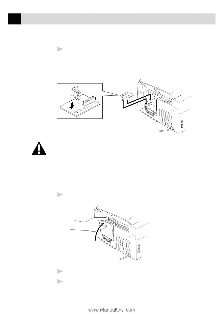
| Installing the Optional Memory Board |
195 |
| Chapter 18 Important Information |
197 |
| Standard Telephone and FCC Notices (For 120V Models Only) |
197 |
| These notices are in effect on models sold and used in the United States only. |
197 |
| Federal Communications Commission(FCC) Declaration of Conformity (For USA Only) |
199 |
| Laser Safety (For 110-120V Models Only) |
199 |
| FDA Regulations |
200 |
| Manufactured |
200 |
| Attention |
200 |
| Industry Canada Compliance Statement (For Canada Only) |
201 |
| International Energy Star Compliance Statement |
201 |
| Important Safety Instructions |
202 |
| Notice – Disclaimer of Warranties |
204 |
| Compilation and Publication Notice |
205 |
| Trademarks |
205 |
| Chapter 19 Troubleshooting and Maintenance |
207 |
| Troubleshooting |
207 |
| Fax-Back System |
207 |
| Brother Home Page |
207 |
| Brother Bulletin Board |
207 |
| Error Messages |
208 |
| Document Jam |
211 |
| Printer Jam |
211 |
| Paper is Jammed in the Multi-purpose Sheet Feeder |
212 |
| Paper is Jammed near the Drum Unit or in the Fuser Unit. |
212 |
| If You Are Having Difficulty with Your MFC |
213 |
| Difficulties Setting up the Software |
220 |
| Problem Using the HP Pavilion PC and the “HP DEMO” Screen Saver |
220 |
| Bi-Directional Parallel Ports (nibble and byte modes) |
220 |
| MFC Connect Failure or Bi-Directional Communication Error |
221 |
| Brother HL-6/6V/10h/630series/660series/960/1260/ WL-660: |
221 |
| HP LaserJet series II, IID, IIP, IIP+, III, IIID or IIIP: |
222 |
| HP LaserJet 4 Plus: |
222 |
| NEC SuperScript 610/660: |
222 |
| EPSON ActionLaser 1100 / 1400: |
223 |
| Lexmark WinWriter 200: |
223 |
| Graphics or Text Is Missing When the Document Is Printed |
224 |
| Packing and Shipping the MFC |
224 |
| Regular Maintenance |
227 |
| Cleaning the Document Scanner |
227 |
| Cleaning the Printer |
228 |
| Cleaning the Drum Unit |
229 |
| Replacing the Toner Cartridge |
230 |
| Toner Empty Indicator |
230 |
| How to Replace the Toner Cartridge |
231 |
| Replacing the Drum Unit |
235 |
| For Customer Service |
240 |
| Chapter 20 Specifications |
241 |
| Product Description |
241 |
| Fax Specifications |
241 |
| Printer Specifications |
242 |
| Electrical and Environment |
243 |
| Parallel Interface Specifications |
244 |
| Resident Fonts |
245 |
| Symbol Sets/Character Sets |
245 |
| Glossary |
247 |
| Index |
253 |

 1
1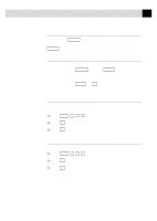 191
191 192
192 193
193 194
194 195
195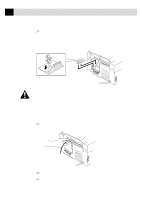 196
196 197
197 198
198 199
199 200
200 201
201