Dell Inspiron 531S Owner's Manual - Page 149
Rotate the heat sink assembly upward gently, and remove it from
 |
View all Dell Inspiron 531S manuals
Add to My Manuals
Save this manual to your list of manuals |
Page 149 highlights
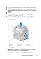
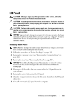
5 Release the clamp grip from the bracket projection on the opposite side. CAUTION: Despite having a plastic shield, the heat sink assembly may be very hot during normal operation. Be sure that it has had sufficient time to cool before you touch it. NOTICE: Strong thermal grease bond may exist between the processor and heat sink. Do not use excessive force to separate the heat sink assembly from the processor to avoid damaging the processor. 6 Rotate the heat sink assembly upward gently, and remove it from the computer. Lay the heat sink assembly down on its top, with the thermal grease facing upward. 1 2 7 3 4 6 5 1 fan 4 bracket 7 clamp lever 2 fan cover 5 clamp grip 3 heat sink 6 bracket projection NOTICE: Unless a new heat sink is required for the new processor, reuse the original heat sink assembly when you replace the processor. 7 Pull the release lever straight up until the processor is released. Removing and Installing Parts 149
-
 1
1 -
2
-
3
-
4
-
5
-
6
-
7
-
8
-
9
-
10
-
11
-
12
-
13
-
14
-
15
-
16
-
17
-
18
-
19
-
20
-
21
-
22
-
23
-
24
-
25
-
26
-
27
-
28
-
29
-
30
-
31
-
32
-
33
-
34
-
35
-
36
-
37
-
38
-
39
-
40
-
41
-
42
-
43
-
44
-
45
-
46
-
47
-
48
-
49
-
50
-
51
-
52
-
53
-
54
-
55
-
56
-
57
-
58
-
59
-
60
-
61
-
62
-
63
-
64
-
65
-
66
-
67
-
68
-
69
-
70
-
71
-
72
-
73
-
74
-
75
-
76
-
77
-
78
-
79
-
80
-
81
-
82
-
83
-
84
-
85
-
86
-
87
-
88
-
89
-
90
-
91
-
92
-
93
-
94
-
95
-
96
-
97
-
98
-
99
-
100
-
101
-
102
-
103
-
104
-
105
-
106
-
107
-
108
-
109
-
110
-
111
-
112
-
113
-
114
-
115
-
116
-
117
-
118
-
119
-
120
-
121
-
122
-
123
-
124
-
125
-
126
-
127
-
128
-
129
-
130
-
131
-
132
-
133
-
134
-
135
-
136
-
137
-
138
-
139
-
140
-
141
-
142
-
143
-
 144
144 -
 145
145 -
 146
146 -
 147
147 -
 148
148 -
 149
149 -
 150
150 -
 151
151 -
 152
152 -
 153
153 -
 154
154 -
155
-
156
-
157
-
158
-
159
-
160
-
161
-
162
-
163
-
164
-
165
-
166
-
167
-
168
-
169
-
170
-
171
-
172
-
173
-
174
-
175
-
176
-
177
-
178
-
179
-
180
-
181
-
182
-
183
-
184
-
185
-
186
-
187
-
188
-
189
-
190
-
191
-
192
-
193
-
194
-
195
-
196
-
197
-
198
-
199
-
200
-
201
-
202
-
203
-
204
-
205
-
206
-
207
-
208
-
209
-
210
-
211
-
212
 |
 |
