Dell PowerEdge 2900 Hardware Owner's Manual (PDF) - Page 108
Remove the CPU processors. See
 |
View all Dell PowerEdge 2900 manuals
Add to My Manuals
Save this manual to your list of manuals |
Page 108 highlights
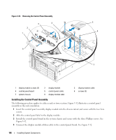
12 If a RAC card is present in the system, disconnect the RAC cables from the system board. Leave the RAC card attached to the expansion-bay bracket. Squeeze the metal tabs on the ends of the RAC cable connector and gently work the connector out of the socket. 13 Remove the expansion-bay bracket: a Pull inward on the latch on the left side of the bracket along the system chassis wall. b Pull the bracket slightly forward to free the bracket from the chassis tabs and lift the bracket up and out of the chassis. 14 Remove the TOE key, if present. See Figure 6-2. 15 Disconnect all cables from the connectors on the front edge of the system board. CAUTION: The DIMMs are hot to the touch for some time after the system has been powered down. Allow time for the DIMMs to cool before handling them. Handle the DIMMs by the card edges and avoid touching the DIMM components. 16 Remove the memory modules. See "Removing Memory Modules" on page 87. 17 Remove the CPU processor(s). See "Replacing a Processor" on page 89. 18 To remove the system board: a Lift up the blue retention pin and slide the system board toward the front of the system to disengage the board from the hooks on the chassis. See Figure 3-33. b Lift the system board out of the system chassis. 108 Installing System Components
-
 1
1 -
2
-
3
-
4
-
5
-
6
-
7
-
8
-
9
-
10
-
11
-
12
-
13
-
14
-
15
-
16
-
17
-
18
-
19
-
20
-
21
-
22
-
23
-
24
-
25
-
26
-
27
-
28
-
29
-
30
-
31
-
32
-
33
-
34
-
35
-
36
-
37
-
38
-
39
-
40
-
41
-
42
-
43
-
44
-
45
-
46
-
47
-
48
-
49
-
50
-
51
-
52
-
53
-
54
-
55
-
56
-
57
-
58
-
59
-
60
-
61
-
62
-
63
-
64
-
65
-
66
-
67
-
68
-
69
-
70
-
71
-
72
-
73
-
74
-
75
-
76
-
77
-
78
-
79
-
80
-
81
-
82
-
83
-
84
-
85
-
86
-
87
-
88
-
89
-
90
-
91
-
92
-
93
-
94
-
95
-
96
-
97
-
98
-
99
-
100
-
101
-
102
-
 103
103 -
 104
104 -
 105
105 -
 106
106 -
 107
107 -
 108
108 -
 109
109 -
 110
110 -
 111
111 -
 112
112 -
 113
113 -
114
-
115
-
116
-
117
-
118
-
119
-
120
-
121
-
122
-
123
-
124
-
125
-
126
-
127
-
128
-
129
-
130
-
131
-
132
-
133
-
134
-
135
-
136
-
137
-
138
-
139
-
140
-
141
-
142
-
143
-
144
-
145
-
146
-
147
-
148
-
149
-
150
-
151
-
152
-
153
-
154
-
155
-
156
-
157
-
158
-
159
-
160
-
161
-
162
-
163
-
164
-
165
-
166
-
167
-
168
-
169
-
170
-
171
-
172
-
173
-
174
-
175
-
176
-
177
-
178
-
179
-
180
-
181
-
182
 |
 |
