Dell PowerEdge 2900 Hardware Owner's Manual (PDF) - Page 53
Installing the Bezel, Opening the System, unlocked position. See - tower
 |
View all Dell PowerEdge 2900 manuals
Add to My Manuals
Save this manual to your list of manuals |
Page 53 highlights
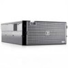
Installing the Bezel 1 Insert the hooks on the end of the bezel into the bezel slots on the right (or bottom) side of the system front plate. See Figure 3-1 for rack systems or Figure 3-2 for tower systems. 2 Rotate the other end of the bezel toward the front panel and press the bezel onto the panel to engage the latch. 3 Lock the bezel. Opening the System CAUTION: Only trained service technicians are authorized to remove the system cover and access any of the components inside the system. See your Product Information Guide for complete information about safety precautions, working inside the computer, and protecting against electrostatic discharge. CAUTION: Whenever you need to lift the system, get others to assist you. To avoid injury, do not attempt to lift the system by yourself. 1 Unless you are installing a hot-plug component such as a cooling fan or power supply, turn off the system and attached peripherals, and disconnect the system from the electrical outlet and peripherals. 2 If you are working with a tower system, place the system on its side on a flat stable surface with the feet overhanging the edge of the work surface. 3 If present, unlock and remove the Kensington cable lock on the back of the system chassis. 4 To remove the system cover, turn the latch release lock on the cover latch counterclockwise to the unlocked position. See Figure 3-4. 5 Lift up on the latch on top of the system. See Figure 3-4. 6 Grasp the cover on both sides and carefully lift the cover away from the system. Closing the System 1 Lift up on the cover latch. 2 Place the cover on top of the system and offset the cover slightly back so that it clears the chassis J hooks and lays flat on the system chassis. See Figure 3-4. 3 Push the latch down to lever the cover into the closed position. 4 Turn the latch release lock clockwise to the locked position. See Figure 3-4. 5 Replace the Kensington cable lock on the back of the chassis. See Figure 1-4 for the location of the lock slot on the back of the chassis. Installing System Components 53
-
 1
1 -
2
-
3
-
4
-
5
-
6
-
7
-
8
-
9
-
10
-
11
-
12
-
13
-
14
-
15
-
16
-
17
-
18
-
19
-
20
-
21
-
22
-
23
-
24
-
25
-
26
-
27
-
28
-
29
-
30
-
31
-
32
-
33
-
34
-
35
-
36
-
37
-
38
-
39
-
40
-
41
-
42
-
43
-
44
-
45
-
46
-
47
-
 48
48 -
 49
49 -
 50
50 -
 51
51 -
 52
52 -
 53
53 -
 54
54 -
 55
55 -
 56
56 -
 57
57 -
 58
58 -
59
-
60
-
61
-
62
-
63
-
64
-
65
-
66
-
67
-
68
-
69
-
70
-
71
-
72
-
73
-
74
-
75
-
76
-
77
-
78
-
79
-
80
-
81
-
82
-
83
-
84
-
85
-
86
-
87
-
88
-
89
-
90
-
91
-
92
-
93
-
94
-
95
-
96
-
97
-
98
-
99
-
100
-
101
-
102
-
103
-
104
-
105
-
106
-
107
-
108
-
109
-
110
-
111
-
112
-
113
-
114
-
115
-
116
-
117
-
118
-
119
-
120
-
121
-
122
-
123
-
124
-
125
-
126
-
127
-
128
-
129
-
130
-
131
-
132
-
133
-
134
-
135
-
136
-
137
-
138
-
139
-
140
-
141
-
142
-
143
-
144
-
145
-
146
-
147
-
148
-
149
-
150
-
151
-
152
-
153
-
154
-
155
-
156
-
157
-
158
-
159
-
160
-
161
-
162
-
163
-
164
-
165
-
166
-
167
-
168
-
169
-
170
-
171
-
172
-
173
-
174
-
175
-
176
-
177
-
178
-
179
-
180
-
181
-
182
 |
 |
