Dell PowerEdge R7525 EMC Installation and Service Manual - Page 34
Serial Communication, Table 26. Integrated Devices details continued
 |
View all Dell PowerEdge R7525 manuals
Add to My Manuals
Save this manual to your list of manuals |
Page 34 highlights
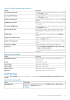
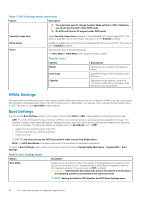
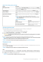
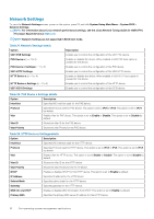
Table 26. Integrated Devices details (continued) Option Description even if add-in graphic cards are installed. When set to Disabled, an add-in graphics card will be used as the primary display. BIOS will output displays to both the primary add-in video and the embedded video during POST and pre-boot environment. The embedded video will then be disabled right before the operating system boots. This option is set to Enabled by default. NOTE: When there are multiple add-in graphic cards installed in the system, the first card discovered during PCI enumeration is selected as the primary video. You might have to re-arrange the cards in the slots in order to control which card is the primary video. Current State of Embedded Video Controller PCIe Preferred IO Bus Enhanced Preferred IO SR-IOV Global Enable OS Watchdog Timer Memory Mapped I/O Limit Slot Disablement Displays the current state of the embedded video controller. The Current State of Embedded Video Controller option is a read-only field. If the Embedded Video Controller is the only display capability in the system (that is, no add-in graphics card is installed), then the Embedded Video Controller is automatically used as the primary display even if the Embedded Video Controller setting is set to Disabled. When set to Enabled, you can provide the Bus address (in decimal) to choose end device for preferred IO Bus. This option is set to Disabled by default. When set to Enabled, the LCLK speed for the root complex where Preferred IO is enabled will automatically be set to 600 MHz (effective 593 MHz). Enables or disables the BIOS configuration of Single Root I/O Virtualization (SR-IOV) devices. This option is set to Disabled by default. If your system stops responding, this watchdog timer aids in the recovery of your operating system. When this option is set to Enabled, the operating system initializes the timer. When this option is set to Disabled (the default), the timer does not have any effect on the system. Controls where MMIO is mapped. The 1 TB option is designed for specific OS which cannot support MMIO over 1 TB. This option is set to 8 TB by default. The default option is the maximum address that the system supports and recommended in most cases. Enables or disables the available PCIe slots on your system. The slot disablement feature controls the configuration of the PCIe cards installed in the specified slot. Slots must be disabled only when the installed peripheral card prevents booting into the operating system or causes delays in system startup. If the slot is disabled, both the Option ROM and UEFI drivers are disabled. Only slots that are present on the system will be available for control. Slot n: Enables or disables or only the boot driver is disabled for the PCIe slot n. This option is set to Enabled by default. Slot Bifurcation Slot Discovery Bifurcation Settings allows Platform Default Bifurcation and Manual bifurcation Control. The default is set to Platform Default Bifurcation. The slot bifurcation field is accessible when set to Manual bifurcation Control and is grayed out when set to Platform Default Bifurcation. Serial Communication To view the Serial Communication screen, power on the system, press F2, and click System Setup Main Menu > System BIOS > Serial Communication. Table 27. Serial Communication details Option Serial Port Address Description Enables you to set the port address for serial devices. . 34 Pre-operating system management applications
-
 1
1 -
2
-
3
-
4
-
5
-
6
-
7
-
8
-
9
-
10
-
11
-
12
-
13
-
14
-
15
-
16
-
17
-
18
-
19
-
20
-
21
-
22
-
23
-
24
-
25
-
26
-
27
-
28
-
 29
29 -
 30
30 -
 31
31 -
 32
32 -
 33
33 -
 34
34 -
 35
35 -
 36
36 -
 37
37 -
 38
38 -
 39
39 -
40
-
41
-
42
-
43
-
44
-
45
-
46
-
47
-
48
-
49
-
50
-
51
-
52
-
53
-
54
-
55
-
56
-
57
-
58
-
59
-
60
-
61
-
62
-
63
-
64
-
65
-
66
-
67
-
68
-
69
-
70
-
71
-
72
-
73
-
74
-
75
-
76
-
77
-
78
-
79
-
80
-
81
-
82
-
83
-
84
-
85
-
86
-
87
-
88
-
89
-
90
-
91
-
92
-
93
-
94
-
95
-
96
-
97
-
98
-
99
-
100
-
101
-
102
-
103
-
104
-
105
-
106
-
107
-
108
-
109
-
110
-
111
-
112
-
113
-
114
-
115
-
116
-
117
-
118
-
119
-
120
-
121
-
122
-
123
-
124
-
125
-
126
-
127
-
128
-
129
-
130
-
131
-
132
-
133
-
134
-
135
-
136
-
137
-
138
-
139
-
140
-
141
-
142
-
143
-
144
-
145
-
146
-
147
-
148
-
149
-
150
-
151
-
152
-
153
-
154
-
155
-
156
-
157
-
158
-
159
-
160
-
161
-
162
-
163
-
164
-
165
-
166
-
167
-
168
-
169
-
170
-
171
-
172
-
173
-
174
-
175
-
176
-
177
-
178
-
179
-
180
-
181
-
182
-
183
-
184
-
185
-
186
-
187
-
188
-
189
-
190
-
191
-
192
-
193
-
194
-
195
-
196
-
197
-
198
-
199
-
200
-
201
-
202
-
203
 |
 |
