Dell PowerEdge T105 Hardware Owner's Manual (PDF) - Page 100
System Board (Service Only Parts Procedure), Removing the System Board
 |
View all Dell PowerEdge T105 manuals
Add to My Manuals
Save this manual to your list of manuals |
Page 100 highlights
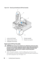
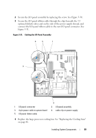
5 Replace the heat sink and shroud assembly. See "Replacing the Processor" on page 82. NOTE: To prevent damaging the processor, clean the heat sink to remove any thermal grease and then apply fresh thermal grease to the processor before installing the heat sink. 6 Close the system. See "Closing the System" on page 47. 7 Reconnect the system to the electrical outlet, and turn on the system. System Board (Service Only Parts Procedure) CAUTION: Only trained service technicians are authorized to remove the system cover and access any of the components inside the system. Before performing any procedure, see your Product Information Guide for complete information about safety precautions, working inside the computer and protecting against electrostatic discharge. CAUTION: The heat sink can get hot during operation. To avoid burns, ensure that the system has sufficient time to cool before removing the system board. Removing the System Board 1 Turn off the system and attached peripherals, and disconnect the system from the electrical outlet. 2 Open the system. See "Opening the System" on page 47. 3 Depending on your configuration, disconnect the following cables from the system board. See Figure 6-2 for connector locations. • Two power-supply cables from the POWER and POWER12V1 connectors • Diskette data cable from the FLOPPY connector • I/O panel cable from the CONTROL-PANEL connector • Processor cooling fan cable from the FAN1 connector • Card cage cooling fan cable from the FAN2 connector • SATA hard-drive data cable(s) from the SATA connector(s) • Intrusion switch cable from the INTRUSION connector 100 Installing System Components
-
 1
1 -
2
-
3
-
4
-
5
-
6
-
7
-
8
-
9
-
10
-
11
-
12
-
13
-
14
-
15
-
16
-
17
-
18
-
19
-
20
-
21
-
22
-
23
-
24
-
25
-
26
-
27
-
28
-
29
-
30
-
31
-
32
-
33
-
34
-
35
-
36
-
37
-
38
-
39
-
40
-
41
-
42
-
43
-
44
-
45
-
46
-
47
-
48
-
49
-
50
-
51
-
52
-
53
-
54
-
55
-
56
-
57
-
58
-
59
-
60
-
61
-
62
-
63
-
64
-
65
-
66
-
67
-
68
-
69
-
70
-
71
-
72
-
73
-
74
-
75
-
76
-
77
-
78
-
79
-
80
-
81
-
82
-
83
-
84
-
85
-
86
-
87
-
88
-
89
-
90
-
91
-
92
-
93
-
94
-
 95
95 -
 96
96 -
 97
97 -
 98
98 -
 99
99 -
 100
100 -
 101
101 -
 102
102 -
 103
103 -
 104
104 -
 105
105 -
106
-
107
-
108
-
109
-
110
-
111
-
112
-
113
-
114
-
115
-
116
-
117
-
118
-
119
-
120
-
121
-
122
-
123
-
124
-
125
-
126
-
127
-
128
-
129
-
130
-
131
-
132
-
133
-
134
-
135
-
136
-
137
-
138
-
139
-
140
-
141
-
142
-
143
-
144
-
145
-
146
-
147
-
148
-
149
-
150
-
151
-
152
-
153
-
154
-
155
-
156
-
157
-
158
-
159
-
160
-
161
-
162
-
163
-
164
-
165
-
166
-
167
-
168
-
169
-
170
-
171
-
172
-
173
-
174
-
175
-
176
-
177
-
178
-
179
-
180
-
181
-
182
-
183
-
184
-
185
-
186
-
187
-
188
-
189
-
190
 |
 |