Dell PowerEdge T105 Hardware Owner's Manual (PDF) - Page 37
Integrated Devices Screen
 |
View all Dell PowerEdge T105 manuals
Add to My Manuals
Save this manual to your list of manuals |
Page 37 highlights
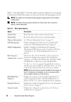
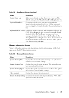
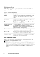
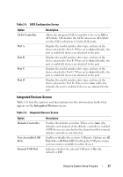
Table 2-5. SATA Configuration Screen Option SATA Controller Port A Port B Port C Port D Description Allows the integrated SATA controller to be set to Off or ATA Mode. Off disables the SATA subsystem. ATA Mode sets the SATA subsystem to Native IDE mode. Displays the model number, drive type, and size of the device attached to Port A. When set to Auto (default), the port is enabled if devices are attached to the port. Displays the model number, drive type, and size of the device attached to Port B. When set to Auto (default), the port is enabled if devices are attached to the port. Displays the model number, drive type, and size of the device attached to Port C. When set to Auto (default), the port is enabled if devices are attached to the port. Displays the model number, drive type, and size of the device attached to Port D. When set to Auto (off is the default), the port is enabled if devices are attached to the port. Integrated Devices Screen Table 2-6 lists the options and descriptions for the information fields that appear on the Integrated Devices screen. Table 2-6. Integrated Devices Screen Option Diskette Controller User Accessible USB Ports Internal USB Port Description Enables the diskette controller. When set to Auto (the default), each channel of the diskette controller is enabled if IDE devices are attached to the channel and the external diskette controller is not detected. Enables or disables the system's USB ports. Options are All Ports On or All Ports Off. Disabling the USB ports makes system resources available for other devices. Indicates whether the internal USB port is On (the default) or Off. Using the System Setup Program 37
-
 1
1 -
2
-
3
-
4
-
5
-
6
-
7
-
8
-
9
-
10
-
11
-
12
-
13
-
14
-
15
-
16
-
17
-
18
-
19
-
20
-
21
-
22
-
23
-
24
-
25
-
26
-
27
-
28
-
29
-
30
-
31
-
 32
32 -
 33
33 -
 34
34 -
 35
35 -
 36
36 -
 37
37 -
 38
38 -
 39
39 -
 40
40 -
 41
41 -
 42
42 -
43
-
44
-
45
-
46
-
47
-
48
-
49
-
50
-
51
-
52
-
53
-
54
-
55
-
56
-
57
-
58
-
59
-
60
-
61
-
62
-
63
-
64
-
65
-
66
-
67
-
68
-
69
-
70
-
71
-
72
-
73
-
74
-
75
-
76
-
77
-
78
-
79
-
80
-
81
-
82
-
83
-
84
-
85
-
86
-
87
-
88
-
89
-
90
-
91
-
92
-
93
-
94
-
95
-
96
-
97
-
98
-
99
-
100
-
101
-
102
-
103
-
104
-
105
-
106
-
107
-
108
-
109
-
110
-
111
-
112
-
113
-
114
-
115
-
116
-
117
-
118
-
119
-
120
-
121
-
122
-
123
-
124
-
125
-
126
-
127
-
128
-
129
-
130
-
131
-
132
-
133
-
134
-
135
-
136
-
137
-
138
-
139
-
140
-
141
-
142
-
143
-
144
-
145
-
146
-
147
-
148
-
149
-
150
-
151
-
152
-
153
-
154
-
155
-
156
-
157
-
158
-
159
-
160
-
161
-
162
-
163
-
164
-
165
-
166
-
167
-
168
-
169
-
170
-
171
-
172
-
173
-
174
-
175
-
176
-
177
-
178
-
179
-
180
-
181
-
182
-
183
-
184
-
185
-
186
-
187
-
188
-
189
-
190
 |
 |
