Dell PowerEdge T105 Hardware Owner's Manual (PDF) - Page 91
Power Supply, Removing the Power Supply - replacement power supply
 |
View all Dell PowerEdge T105 manuals
Add to My Manuals
Save this manual to your list of manuals |
Page 91 highlights
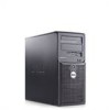
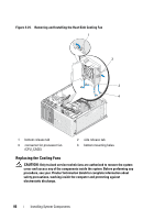
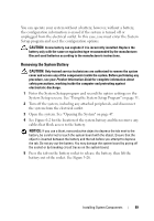
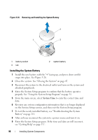
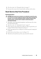
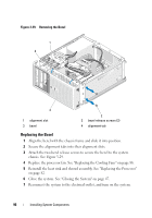
10 Properly dispose of the old battery. For more information, see your Product Information Guide. Power Supply Removing the Power Supply CAUTION: Only trained service technicians are authorized to remove the system cover and access any of the components inside the system. Before performing any procedure, see your Product Information Guide for complete information about safety precautions, working inside the computer and protecting against electrostatic discharge. 1 Turn off the system and attached peripherals, and disconnect the system from the electrical outlet. 2 Open the system. See "Opening the System" on page 47. 3 Depending on your system configuration, disconnect the following power cables: • P1 and P2 to the system board • P3 and P5 to the SATA or SAS drives • P7 to the diskette drive • P8, P9, and P10 to the optical and tape drives NOTE: Note the routing of the DC power cables underneath the tabs in the system frame as you release the tabs and remove the cables from the system board and drives. You must route these cables properly when you replace them to prevent their being pinched or crimped. 4 Remove the heat sink and shroud assembly. Loosen the two captive screws holding the heat sink and shroud assembly in place. These captive screws are adjacent to the processor cooling fan housing. See Figure 3-21. 5 Tilt the heat sink and shroud assembly away from the fan housing and lift it out. 6 Remove the I/O panel and SATA cables (if present) attached to the routing clips on the side of the power supply. Installing System Components 91
-
 1
1 -
2
-
3
-
4
-
5
-
6
-
7
-
8
-
9
-
10
-
11
-
12
-
13
-
14
-
15
-
16
-
17
-
18
-
19
-
20
-
21
-
22
-
23
-
24
-
25
-
26
-
27
-
28
-
29
-
30
-
31
-
32
-
33
-
34
-
35
-
36
-
37
-
38
-
39
-
40
-
41
-
42
-
43
-
44
-
45
-
46
-
47
-
48
-
49
-
50
-
51
-
52
-
53
-
54
-
55
-
56
-
57
-
58
-
59
-
60
-
61
-
62
-
63
-
64
-
65
-
66
-
67
-
68
-
69
-
70
-
71
-
72
-
73
-
74
-
75
-
76
-
77
-
78
-
79
-
80
-
81
-
82
-
83
-
84
-
85
-
 86
86 -
 87
87 -
 88
88 -
 89
89 -
 90
90 -
 91
91 -
 92
92 -
 93
93 -
 94
94 -
 95
95 -
 96
96 -
97
-
98
-
99
-
100
-
101
-
102
-
103
-
104
-
105
-
106
-
107
-
108
-
109
-
110
-
111
-
112
-
113
-
114
-
115
-
116
-
117
-
118
-
119
-
120
-
121
-
122
-
123
-
124
-
125
-
126
-
127
-
128
-
129
-
130
-
131
-
132
-
133
-
134
-
135
-
136
-
137
-
138
-
139
-
140
-
141
-
142
-
143
-
144
-
145
-
146
-
147
-
148
-
149
-
150
-
151
-
152
-
153
-
154
-
155
-
156
-
157
-
158
-
159
-
160
-
161
-
162
-
163
-
164
-
165
-
166
-
167
-
168
-
169
-
170
-
171
-
172
-
173
-
174
-
175
-
176
-
177
-
178
-
179
-
180
-
181
-
182
-
183
-
184
-
185
-
186
-
187
-
188
-
189
-
190
 |
 |
