Dell PowerEdge T105 Hardware Owner's Manual (PDF) - Page 82
Replacing the Processor, npack the new processor
 |
View all Dell PowerEdge T105 manuals
Add to My Manuals
Save this manual to your list of manuals |
Page 82 highlights
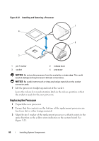
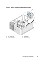
Figure 3-22. Installing and Removing a Processor 1 4 2 3 1 pin 1 marker 3 socket 2 release lever 4 processor NOTICE: Do not pry the processor from the socket by a single edge. This could result in damage to the processor's delicate connections. NOTICE: Be careful not to touch or drop any foreign materials on the socket connector pads. 7 Lift the processor straight up and out of the socket. Leave the release lever and retention latch in the release position so that the socket is ready for the new processor. Replacing the Processor 1 Unpack the new processor. 2 Ensure that the contacts on the bottom of the replacement processor are free from dirt or other foreign material. 3 Align the pin 1 marker of the replacement processor so that it points in the same direction as the yellow arrow indicator on the system board. See Figure 3-22. 82 Installing System Components
-
 1
1 -
2
-
3
-
4
-
5
-
6
-
7
-
8
-
9
-
10
-
11
-
12
-
13
-
14
-
15
-
16
-
17
-
18
-
19
-
20
-
21
-
22
-
23
-
24
-
25
-
26
-
27
-
28
-
29
-
30
-
31
-
32
-
33
-
34
-
35
-
36
-
37
-
38
-
39
-
40
-
41
-
42
-
43
-
44
-
45
-
46
-
47
-
48
-
49
-
50
-
51
-
52
-
53
-
54
-
55
-
56
-
57
-
58
-
59
-
60
-
61
-
62
-
63
-
64
-
65
-
66
-
67
-
68
-
69
-
70
-
71
-
72
-
73
-
74
-
75
-
76
-
 77
77 -
 78
78 -
 79
79 -
 80
80 -
 81
81 -
 82
82 -
 83
83 -
 84
84 -
 85
85 -
 86
86 -
 87
87 -
88
-
89
-
90
-
91
-
92
-
93
-
94
-
95
-
96
-
97
-
98
-
99
-
100
-
101
-
102
-
103
-
104
-
105
-
106
-
107
-
108
-
109
-
110
-
111
-
112
-
113
-
114
-
115
-
116
-
117
-
118
-
119
-
120
-
121
-
122
-
123
-
124
-
125
-
126
-
127
-
128
-
129
-
130
-
131
-
132
-
133
-
134
-
135
-
136
-
137
-
138
-
139
-
140
-
141
-
142
-
143
-
144
-
145
-
146
-
147
-
148
-
149
-
150
-
151
-
152
-
153
-
154
-
155
-
156
-
157
-
158
-
159
-
160
-
161
-
162
-
163
-
164
-
165
-
166
-
167
-
168
-
169
-
170
-
171
-
172
-
173
-
174
-
175
-
176
-
177
-
178
-
179
-
180
-
181
-
182
-
183
-
184
-
185
-
186
-
187
-
188
-
189
-
190
 |
 |
