Dell PowerEdge T105 Hardware Owner's Manual (PDF) - Page 56
enabled. See Using the System Setup Program
 |
View all Dell PowerEdge T105 manuals
Add to My Manuals
Save this manual to your list of manuals |
Page 56 highlights
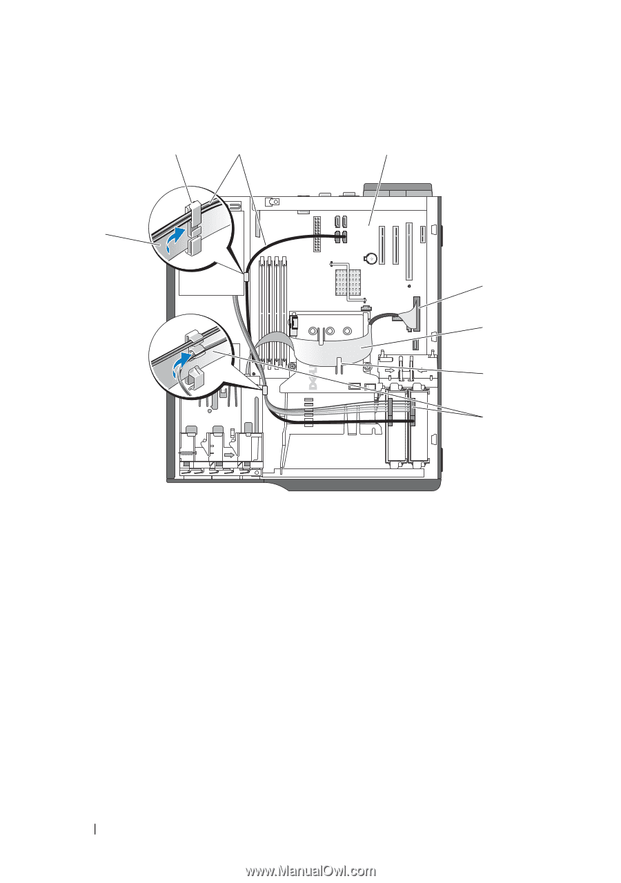
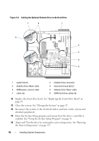
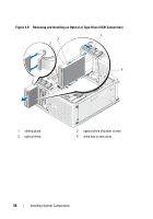
Figure 3-8. Cabling the Optional Diskette Drive to the Hard Drive 7 8 1 6 2 3 4 5 1 system board 3 diskette drive ribbon cable 5 SATA power convert cable 7 cable clip 2 diskette drive connector 4 heat sink shroud tab (2) 6 diskette drive ribbon cable 8 SATA hard drive cables (2) 12 Replace the front drive bezel. See "Replacing the Front Drive Bezel" on page 49. 13 Close the system. See "Closing the System" on page 47. 14 Reconnect the system to the electrical outlet, and turn on the system and attached peripherals. 15 Enter the System Setup program and ensure that the drive's controller is enabled. See "Using the System Setup Program" on page 31. 16 (Optional) Test the drive by running the system diagnostics. See "Running the System Diagnostics" on page 127. 56 Installing System Components
-
 1
1 -
2
-
3
-
4
-
5
-
6
-
7
-
8
-
9
-
10
-
11
-
12
-
13
-
14
-
15
-
16
-
17
-
18
-
19
-
20
-
21
-
22
-
23
-
24
-
25
-
26
-
27
-
28
-
29
-
30
-
31
-
32
-
33
-
34
-
35
-
36
-
37
-
38
-
39
-
40
-
41
-
42
-
43
-
44
-
45
-
46
-
47
-
48
-
49
-
50
-
 51
51 -
 52
52 -
 53
53 -
 54
54 -
 55
55 -
 56
56 -
 57
57 -
 58
58 -
 59
59 -
 60
60 -
 61
61 -
62
-
63
-
64
-
65
-
66
-
67
-
68
-
69
-
70
-
71
-
72
-
73
-
74
-
75
-
76
-
77
-
78
-
79
-
80
-
81
-
82
-
83
-
84
-
85
-
86
-
87
-
88
-
89
-
90
-
91
-
92
-
93
-
94
-
95
-
96
-
97
-
98
-
99
-
100
-
101
-
102
-
103
-
104
-
105
-
106
-
107
-
108
-
109
-
110
-
111
-
112
-
113
-
114
-
115
-
116
-
117
-
118
-
119
-
120
-
121
-
122
-
123
-
124
-
125
-
126
-
127
-
128
-
129
-
130
-
131
-
132
-
133
-
134
-
135
-
136
-
137
-
138
-
139
-
140
-
141
-
142
-
143
-
144
-
145
-
146
-
147
-
148
-
149
-
150
-
151
-
152
-
153
-
154
-
155
-
156
-
157
-
158
-
159
-
160
-
161
-
162
-
163
-
164
-
165
-
166
-
167
-
168
-
169
-
170
-
171
-
172
-
173
-
174
-
175
-
176
-
177
-
178
-
179
-
180
-
181
-
182
-
183
-
184
-
185
-
186
-
187
-
188
-
189
-
190
 |
 |