Dell PowerEdge T105 Hardware Owner's Manual (PDF) - Page 98
Replacing the I/O Panel Assembly
 |
View all Dell PowerEdge T105 manuals
Add to My Manuals
Save this manual to your list of manuals |
Page 98 highlights
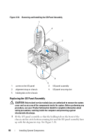
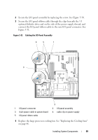
Figure 3-30. Removing and Installing the I/O Panel Assembly 1 2 3 1 screw on the I/O panel 3 alignment stop on chassis 5 holding tab on the chassis 4 5 2 I/O panel assembly 4 I/O panel securing slot Replacing the I/O Panel Assembly CAUTION: Only trained service technicians are authorized to remove the system cover and access any of the components inside the system. Before performing any procedure, see your Product Information Guide for complete information about safety precautions, working inside the computer and protecting against electrostatic discharge. 1 Fit the I/O panel assembly so that the holding tab on the front of the chassis catches at its bottom securing slot and the I/O panel assembly lines up with the alignment stop. See Figure 3-30. 98 Installing System Components
-
 1
1 -
2
-
3
-
4
-
5
-
6
-
7
-
8
-
9
-
10
-
11
-
12
-
13
-
14
-
15
-
16
-
17
-
18
-
19
-
20
-
21
-
22
-
23
-
24
-
25
-
26
-
27
-
28
-
29
-
30
-
31
-
32
-
33
-
34
-
35
-
36
-
37
-
38
-
39
-
40
-
41
-
42
-
43
-
44
-
45
-
46
-
47
-
48
-
49
-
50
-
51
-
52
-
53
-
54
-
55
-
56
-
57
-
58
-
59
-
60
-
61
-
62
-
63
-
64
-
65
-
66
-
67
-
68
-
69
-
70
-
71
-
72
-
73
-
74
-
75
-
76
-
77
-
78
-
79
-
80
-
81
-
82
-
83
-
84
-
85
-
86
-
87
-
88
-
89
-
90
-
91
-
92
-
 93
93 -
 94
94 -
 95
95 -
 96
96 -
 97
97 -
 98
98 -
 99
99 -
 100
100 -
 101
101 -
 102
102 -
 103
103 -
104
-
105
-
106
-
107
-
108
-
109
-
110
-
111
-
112
-
113
-
114
-
115
-
116
-
117
-
118
-
119
-
120
-
121
-
122
-
123
-
124
-
125
-
126
-
127
-
128
-
129
-
130
-
131
-
132
-
133
-
134
-
135
-
136
-
137
-
138
-
139
-
140
-
141
-
142
-
143
-
144
-
145
-
146
-
147
-
148
-
149
-
150
-
151
-
152
-
153
-
154
-
155
-
156
-
157
-
158
-
159
-
160
-
161
-
162
-
163
-
164
-
165
-
166
-
167
-
168
-
169
-
170
-
171
-
172
-
173
-
174
-
175
-
176
-
177
-
178
-
179
-
180
-
181
-
182
-
183
-
184
-
185
-
186
-
187
-
188
-
189
-
190
 |
 |
