Epson LQ-300 User Manual - Page 93
Serial pin assignments, DTR protocol, XON/XOFF protocol
 |
View all Epson LQ-300 manuals
Add to My Manuals
Save this manual to your list of manuals |
Page 93 highlights
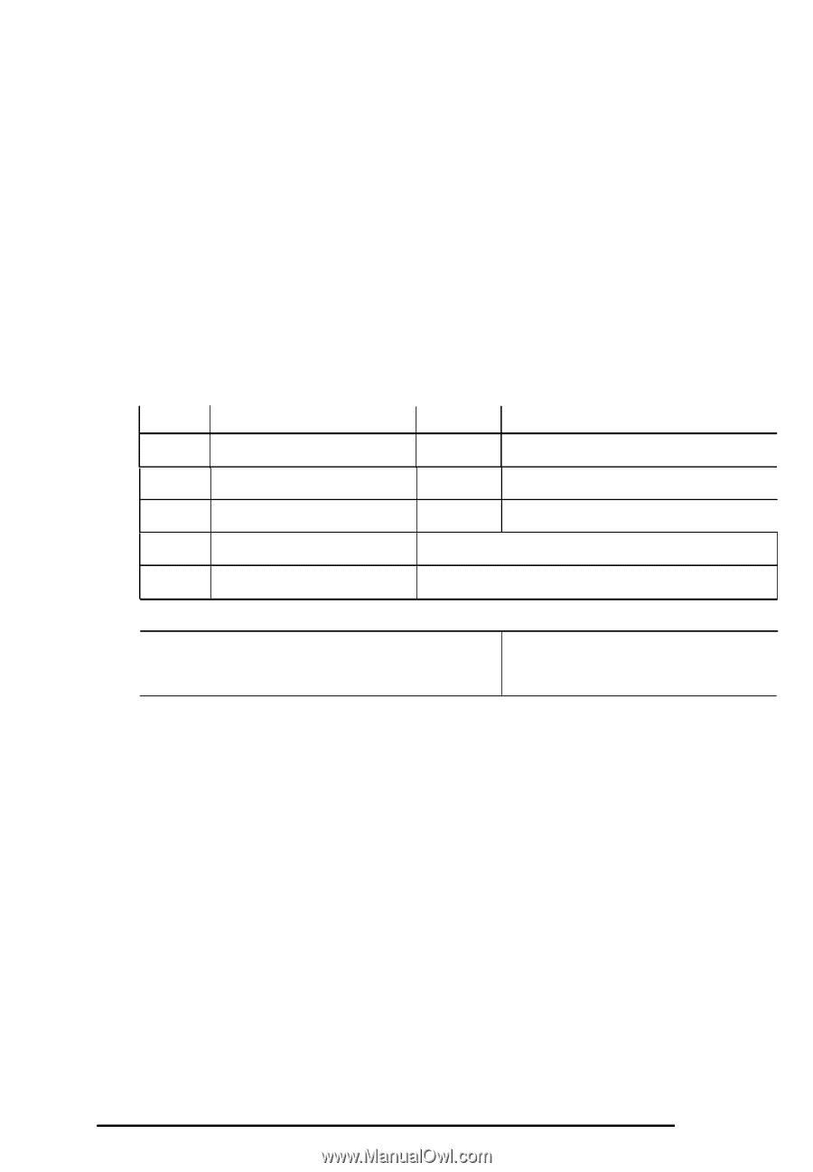
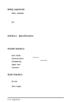
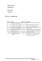
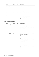
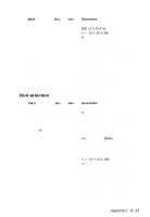
Synchronization: Handshaking: Parity check Connector: Asynchronous DTR protocol, XON/XOFF protocol, ETX/ACK protocol (selectable) Odd, even, or none (selectable) EIA standard, 25-pin, D-SUB, female connector Serial pin assignments The following table lists the serial connector pin assignments and describes their respective interface signals. Pin No. 1 2 3 4 7 11 20 Signal Protective Ground (FG) Transmitted Data (TXD/SD) Received Data (RXD/RD) Request to Send (RTS/RS) Signal Ground (SG) Direction - out In out - Reverse Channel out Data Terminal Ready out (DTR/ER) Description Printer's chassis ground Printer has transmitted serial data Printer has received serial data Always positive Return path for data control signals Connected to Pin 20 Positive when the printer is ready to accept data, and negative when the printer is not ready Appendix A-9
-
 1
1 -
2
-
3
-
4
-
5
-
6
-
7
-
8
-
9
-
10
-
11
-
12
-
13
-
14
-
15
-
16
-
17
-
18
-
19
-
20
-
21
-
22
-
23
-
24
-
25
-
26
-
27
-
28
-
29
-
30
-
31
-
32
-
33
-
34
-
35
-
36
-
37
-
38
-
39
-
40
-
41
-
42
-
43
-
44
-
45
-
46
-
47
-
48
-
49
-
50
-
51
-
52
-
53
-
54
-
55
-
56
-
57
-
58
-
59
-
60
-
61
-
62
-
63
-
64
-
65
-
66
-
67
-
68
-
69
-
70
-
71
-
72
-
73
-
74
-
75
-
76
-
77
-
78
-
79
-
80
-
81
-
82
-
83
-
84
-
85
-
86
-
87
-
 88
88 -
 89
89 -
 90
90 -
 91
91 -
 92
92 -
 93
93 -
 94
94 -
 95
95 -
 96
96 -
 97
97 -
 98
98 -
99
-
100
-
101
-
102
-
103
-
104
-
105
-
106
-
107
-
108
-
109
-
110
-
111
-
112
-
113
-
114
-
115
-
116
-
117
 |
 |