HP 2100 Service Manual - Page 189
Fusing Assembly Removal
 |
UPC - 873662008284
View all HP 2100 manuals
Add to My Manuals
Save this manual to your list of manuals |
Page 189 highlights
Fusing Assembly Removal Turn the power off and unplug the power cord before removing the fusing assembly. After turning the power off, let the fusing assembly cool down for several minutes. Do not insert metallic objects into the opening shown in figure 7-34. The print engine test button is located on the back of the printer as shown in figure 7-35. Figure 7-34Not a Print Engine Test Button Figure 7-35Print Engine Test Button 1 Remove the following assemblies: • Remove the DIMM cover. (See "DIMM Cover Removal" (page 172) for instructions.) • Remove the rear cover. (See "Rear Cover Removal" (page 177) for instructions.) C4170-90959 Parts Removal Tree 179
-
 1
1 -
2
-
3
-
4
-
5
-
6
-
7
-
8
-
9
-
10
-
11
-
12
-
13
-
14
-
15
-
16
-
17
-
18
-
19
-
20
-
21
-
22
-
23
-
24
-
25
-
26
-
27
-
28
-
29
-
30
-
31
-
32
-
33
-
34
-
35
-
36
-
37
-
38
-
39
-
40
-
41
-
42
-
43
-
44
-
45
-
46
-
47
-
48
-
49
-
50
-
51
-
52
-
53
-
54
-
55
-
56
-
57
-
58
-
59
-
60
-
61
-
62
-
63
-
64
-
65
-
66
-
67
-
68
-
69
-
70
-
71
-
72
-
73
-
74
-
75
-
76
-
77
-
78
-
79
-
80
-
81
-
82
-
83
-
84
-
85
-
86
-
87
-
88
-
89
-
90
-
91
-
92
-
93
-
94
-
95
-
96
-
97
-
98
-
99
-
100
-
101
-
102
-
103
-
104
-
105
-
106
-
107
-
108
-
109
-
110
-
111
-
112
-
113
-
114
-
115
-
116
-
117
-
118
-
119
-
120
-
121
-
122
-
123
-
124
-
125
-
126
-
127
-
128
-
129
-
130
-
131
-
132
-
133
-
134
-
135
-
136
-
137
-
138
-
139
-
140
-
141
-
142
-
143
-
144
-
145
-
146
-
147
-
148
-
149
-
150
-
151
-
152
-
153
-
154
-
155
-
156
-
157
-
158
-
159
-
160
-
161
-
162
-
163
-
164
-
165
-
166
-
167
-
168
-
169
-
170
-
171
-
172
-
173
-
174
-
175
-
176
-
177
-
178
-
179
-
180
-
181
-
182
-
183
-
 184
184 -
 185
185 -
 186
186 -
 187
187 -
 188
188 -
 189
189 -
 190
190 -
 191
191 -
 192
192 -
 193
193 -
 194
194 -
195
-
196
-
197
-
198
-
199
-
200
-
201
-
202
-
203
-
204
-
205
-
206
-
207
-
208
-
209
-
210
-
211
-
212
-
213
-
214
-
215
-
216
-
217
-
218
-
219
-
220
-
221
-
222
-
223
-
224
-
225
-
226
-
227
-
228
-
229
-
230
-
231
-
232
-
233
-
234
-
235
-
236
-
237
-
238
-
239
-
240
-
241
-
242
-
243
-
244
-
245
-
246
-
247
-
248
-
249
-
250
-
251
-
252
-
253
-
254
-
255
-
256
-
257
-
258
-
259
-
260
-
261
-
262
-
263
-
264
-
265
-
266
-
267
-
268
-
269
-
270
-
271
-
272
-
273
-
274
-
275
-
276
-
277
-
278
-
279
-
280
-
281
-
282
-
283
-
284
-
285
-
286
-
287
-
288
-
289
-
290
-
291
-
292
-
293
-
294
-
295
-
296
-
297
-
298
-
299
-
300
-
301
-
302
-
303
-
304
-
305
-
306
-
307
-
308
-
309
-
310
 |
 |

C4170-90959
Parts Removal Tree
179
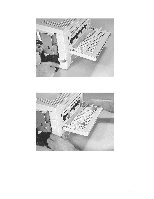
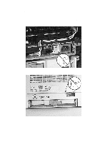
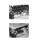
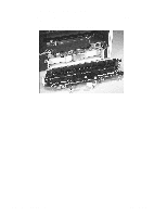
Fusing Assembly Removal
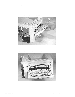
Turn the power off and unplug the power cord before removing the fusing assembly. After
turning the power off, let the fusing assembly cool down for several minutes.
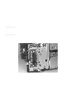
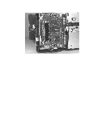
Do not insert metallic objects into the opening shown in figure 7-34. The print engine test
button is located on the back of the printer as shown in figure 7-35.
Figure 7-34
Not a Print Engine Test Button
Figure 7-35
Print Engine Test Button
1
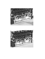
Remove the following assemblies:
•
Remove the DIMM cover. (See “DIMM Cover Removal” (page 172) for instructions.)
•
Remove the rear cover. (See “Rear Cover Removal” (page 177) for instructions.)