HP DL120 ProLiant DL120 Generation 5 Server Maintenance and Service Guide - Page 90
System board, Description, Component code
 |
UPC - 884962061909
View all HP DL120 manuals
Add to My Manuals
Save this manual to your list of manuals |
Page 90 highlights
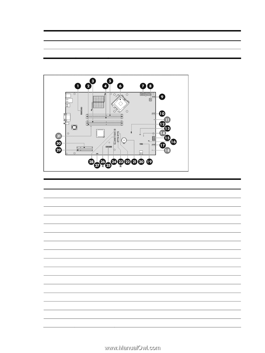
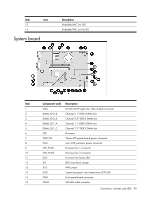
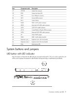
Item Icon 13 14 System board Description Embedded NIC link LED Embedded NIC activity LED Item 1 2 3 4 5 6 7 8 9 10 11 12 13 14 15 16 Component code CN6 DIMM_CH2_B DIMM_CH2_D DIMM_CH1_A DIMM_CH1_C CPU PWR_CN CN4 CPU_FAN1 CPU_FAN2 LED1 JP5 JP13 LED3 CN8 CN26 Description DL120 G5 HP Lights-Out 100c module connector Channel 2 1st DDR II DIMM slot Channel 2 2nd DDR II DIMM slot Channel 1 1st DDR II DIMM slot Channel 1 2nd DDR II DIMM slot Processor 20-pin ATX system board power connector 4-pin ATX processor power connector Processor fan 1 connector Processor fan 2 connector Processor fan failure LED BIOS boot block jumper NMI jumper System/processor over temperature (OTP) LED Front panel board connector SAS LED cable connector Connectors, switches, and LEDs 90
-
 1
1 -
2
-
3
-
4
-
5
-
6
-
7
-
8
-
9
-
10
-
11
-
12
-
13
-
14
-
15
-
16
-
17
-
18
-
19
-
20
-
21
-
22
-
23
-
24
-
25
-
26
-
27
-
28
-
29
-
30
-
31
-
32
-
33
-
34
-
35
-
36
-
37
-
38
-
39
-
40
-
41
-
42
-
43
-
44
-
45
-
46
-
47
-
48
-
49
-
50
-
51
-
52
-
53
-
54
-
55
-
56
-
57
-
58
-
59
-
60
-
61
-
62
-
63
-
64
-
65
-
66
-
67
-
68
-
69
-
70
-
71
-
72
-
73
-
74
-
75
-
76
-
77
-
78
-
79
-
80
-
81
-
82
-
83
-
84
-
 85
85 -
 86
86 -
 87
87 -
 88
88 -
 89
89 -
 90
90 -
 91
91 -
 92
92 -
 93
93 -
 94
94 -
 95
95 -
96
-
97
-
98
-
99
-
100
-
101
-
102
-
103
-
104
-
105
-
106
-
107
-
108
 |
 |