HP LaserJet Pro CP1525 Service Manual - Page 103
Control panel message, Status alert, Description, Recommended action, 10 Fuser error, unit J201, J202
 |
View all HP LaserJet Pro CP1525 manuals
Add to My Manuals
Save this manual to your list of manuals |
Page 103 highlights
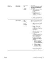
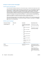
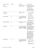
Control panel message 50.10 Fuser error Status alert 50.12 Fuser error 50.2 Fuser error ENWW Description Fuser is defective (abnormal high temperature of the thermistor) Fuser is defective (Fuser 1 pressure release mechanism failure) Fuser is defective (warm-up failure) Recommended action 1. Reconnect the connectors of the fuser unit (J802) and DC controller PCA (J104). 2. Measure the resistance between the connector J802-1 and J802-3 on the fuser. If the resistance is not within the range from approximately 220 kΩ to 660 kΩ (at ambient temperatures), replace the fuser. 3. Replace the fuser power supply unit. 1. Reconnect the connectors of the DC controller PCA (J110, J115). 2. Check the sensor flag of the fuser pressure release sensor. If the sensor flag is damaged, replace it. 3. Replace the fuser motor. 4. Replace the high-voltage power supply unit. 5. Replace the fuser unit. 1. Reconnect the connectors of the fuser unit (J802) and DC controller PCA (J104). 2. Measure the resistance between the connector J801-1 and J801-3 on the fusier. If the resistance is not within the range from approximately 220 kΩ to 660 kΩ (at ambient temperatures), replace the fuser. 3. Reconnect the connectors of the fuser power supply unit (J201, J202, J203). 4. Measure the resistance between the connector J801-1 and J801-2 on the fuser. If the resistance is not within the range from approximately 21 Ω to 25 Ω (at ambient temperatures), replace the fuser. 5. If the message persists, replace the fuser power supply unit. Tools for troubleshooting 85
-
 1
1 -
2
-
3
-
4
-
5
-
6
-
7
-
8
-
9
-
10
-
11
-
12
-
13
-
14
-
15
-
16
-
17
-
18
-
19
-
20
-
21
-
22
-
23
-
24
-
25
-
26
-
27
-
28
-
29
-
30
-
31
-
32
-
33
-
34
-
35
-
36
-
37
-
38
-
39
-
40
-
41
-
42
-
43
-
44
-
45
-
46
-
47
-
48
-
49
-
50
-
51
-
52
-
53
-
54
-
55
-
56
-
57
-
58
-
59
-
60
-
61
-
62
-
63
-
64
-
65
-
66
-
67
-
68
-
69
-
70
-
71
-
72
-
73
-
74
-
75
-
76
-
77
-
78
-
79
-
80
-
81
-
82
-
83
-
84
-
85
-
86
-
87
-
88
-
89
-
90
-
91
-
92
-
93
-
94
-
95
-
96
-
97
-
 98
98 -
 99
99 -
 100
100 -
 101
101 -
 102
102 -
 103
103 -
 104
104 -
 105
105 -
 106
106 -
 107
107 -
 108
108 -
109
-
110
-
111
-
112
-
113
-
114
-
115
-
116
-
117
-
118
-
119
-
120
-
121
-
122
-
123
-
124
-
125
-
126
-
127
-
128
-
129
-
130
-
131
-
132
-
133
-
134
-
135
-
136
-
137
-
138
-
139
-
140
-
141
-
142
-
143
-
144
-
145
-
146
-
147
-
148
-
149
-
150
-
151
-
152
-
153
-
154
-
155
-
156
-
157
-
158
-
159
-
160
-
161
-
162
-
163
-
164
-
165
-
166
-
167
-
168
-
169
-
170
-
171
-
172
-
173
-
174
-
175
-
176
-
177
-
178
-
179
-
180
-
181
-
182
-
183
-
184
-
185
-
186
-
187
-
188
-
189
-
190
-
191
-
192
 |
 |
