HP P4000 HP Smart Array SAS controllers for Integrity servers support guide - Page 21
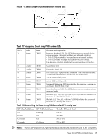
Table 1-10 Determining the Smart Array P812 controller CPU activity level
 |
View all HP P4000 manuals
Add to My Manuals
Save this manual to your list of manuals |
Page 21 highlights
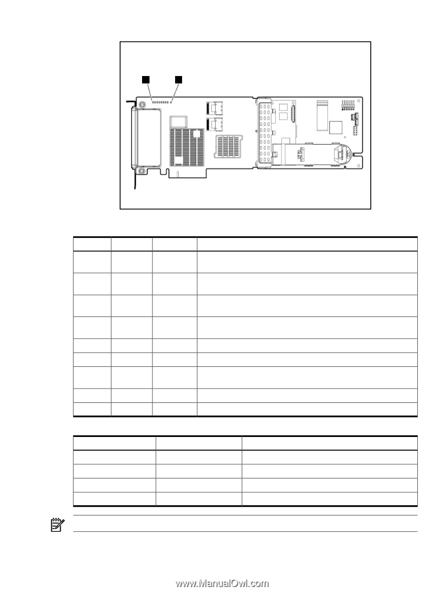
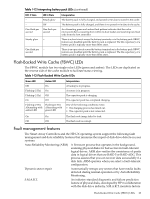
Figure 1-11 Smart Array P812 controller board runtime LEDs 1 9 Table 1-9 Interpreting Smart Array P812 runtime LEDs LED ID 1 2 3 4 5 6 7 8 9 Color Green Green Green Green Green Green Amber Amber Green Name CR76 CR75 CR74 CR73 CR72 CR71 CR78 CR77 CR82 LED name and interpretation Idle Task LED. This LED, with item 7 (CR504), indicates the amount of controller CPU activity. See Table 1-10. Gas Pedal LED. This LED, with item 10 (CR503), indicates the amount of controller CPU activity. See Table 1-10. Controller Heartbeat LED. This LED flashes every two seconds to indicate controller health. Pending Command LED. Indicates that the controller is working on a command from the host driver. Activity LED for SAS port 1. Activity LED for SAS port 2. Disk Failure LED. A physical disk connected to the controller has failed. See the Fault LED on each disk to determine the failed disk. Diagnostics Error LED. One of the server diagnostics has detected an error. MIPS Ready LED. The embedded SAS expander is active. Table 1-10 Determining the Smart Array P812 controller CPU activity level LED 2 (Gas Pedal) Status Off Flashing On Steady On steady LED 1 (Idle Task) Status Flashing Off Off On Steady Controller CPU activity level 0 to 25% 25 to 50% 50% to 75% 75% to 100% NOTE: During server power on, each runtime LED illuminates randomly until POST completes. Smart Array P812 controller features 21
-
 1
1 -
2
-
3
-
4
-
5
-
6
-
7
-
8
-
9
-
10
-
11
-
12
-
13
-
14
-
15
-
 16
16 -
 17
17 -
 18
18 -
 19
19 -
 20
20 -
 21
21 -
 22
22 -
 23
23 -
 24
24 -
 25
25 -
 26
26 -
27
-
28
-
29
-
30
-
31
-
32
-
33
-
34
-
35
-
36
-
37
-
38
-
39
-
40
-
41
-
42
-
43
-
44
-
45
-
46
-
47
-
48
-
49
-
50
-
51
-
52
-
53
-
54
-
55
-
56
-
57
-
58
-
59
-
60
-
61
-
62
-
63
-
64
-
65
-
66
-
67
-
68
-
69
-
70
-
71
-
72
-
73
-
74
-
75
-
76
-
77
-
78
-
79
-
80
-
81
-
82
-
83
-
84
-
85
-
86
-
87
-
88
-
89
-
90
-
91
-
92
-
93
-
94
-
95
-
96
-
97
-
98
-
99
-
100
-
101
-
102
-
103
-
104
-
105
-
106
-
107
-
108
-
109
-
110
-
111
-
112
-
113
-
114
-
115
-
116
-
117
-
118
-
119
-
120
-
121
-
122
-
123
-
124
-
125
-
126
-
127
-
128
-
129
-
130
-
131
-
132
-
133
-
134
-
135
-
136
-
137
-
138
-
139
-
140
-
141
-
142
 |
 |