HP P4000 HP Smart Array SAS controllers for Integrity servers support guide - Page 22
Battery pack LEDs, Smart Array battery pack LEDs, Table 1-11 Battery pack LEDs - quickspecs
 |
View all HP P4000 manuals
Add to My Manuals
Save this manual to your list of manuals |
Page 22 highlights
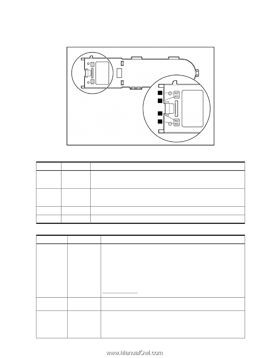
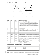
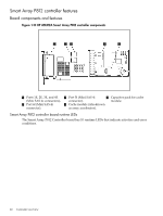
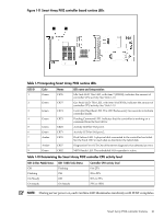
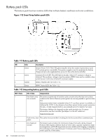
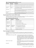
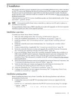
Battery pack LEDs The battery pack has four runtime LEDs that indicate battery readiness and error conditions. Figure 1-12 Smart Array battery pack LEDs 1 2 3 4 Table 1-11 Battery pack LEDs LED Color Description 1 Green System Power LED. This LED glows steadily when the system is powered on and 12 V system power is available. This power supply is used to maintain the battery charge and provide supplementary power to the cache microcontroller. 2 Green Auxiliary Power LED. This LED glows steadily when 3.3 V auxiliary voltage is detected. The auxiliary voltage is used to preserve BBWC data and is available when system power cords are connected to a power supply. 3 Amber Battery Health LED. See Table 1-12. 4 Green BBWC Status LED. See Table 1-12. Table 1-12 Interpreting battery pack LEDs LED 3 State -- LED 4 State Interpretation One flash every two seconds The system is powered off and the cache contains data that has not yet been written to the drives. Restore system power as soon as possible to prevent data loss. Data preservation time is extended when 3.3 V auxiliary power is available, as indicated by LED 2. In the absence of auxiliary power, battery power preserves the data. A fully-charged battery can normally preserve data for two days. The battery lifetime also depends on the cache module size. For more information, see the controller QuickSpecs on the HP website at: http://www.hp.com -- Flash twice, then The cache microcontroller is waiting for the host controller to communicate. pause -- One flash per The battery pack is below the minimum charge level and is being charged. second Features that require a battery (such as write cache, capacity expansion, stripe size migration, and RAID migration) are unavailable until charging is complete. The recharge process takes between 15 minutes and 2 hours, depending on the initial capacity of the battery. 22 Controller overview
-
 1
1 -
2
-
3
-
4
-
5
-
6
-
7
-
8
-
9
-
10
-
11
-
12
-
13
-
14
-
15
-
16
-
 17
17 -
 18
18 -
 19
19 -
 20
20 -
 21
21 -
 22
22 -
 23
23 -
 24
24 -
 25
25 -
 26
26 -
 27
27 -
28
-
29
-
30
-
31
-
32
-
33
-
34
-
35
-
36
-
37
-
38
-
39
-
40
-
41
-
42
-
43
-
44
-
45
-
46
-
47
-
48
-
49
-
50
-
51
-
52
-
53
-
54
-
55
-
56
-
57
-
58
-
59
-
60
-
61
-
62
-
63
-
64
-
65
-
66
-
67
-
68
-
69
-
70
-
71
-
72
-
73
-
74
-
75
-
76
-
77
-
78
-
79
-
80
-
81
-
82
-
83
-
84
-
85
-
86
-
87
-
88
-
89
-
90
-
91
-
92
-
93
-
94
-
95
-
96
-
97
-
98
-
99
-
100
-
101
-
102
-
103
-
104
-
105
-
106
-
107
-
108
-
109
-
110
-
111
-
112
-
113
-
114
-
115
-
116
-
117
-
118
-
119
-
120
-
121
-
122
-
123
-
124
-
125
-
126
-
127
-
128
-
129
-
130
-
131
-
132
-
133
-
134
-
135
-
136
-
137
-
138
-
139
-
140
-
141
-
142
 |
 |