HP P4000 HP Smart Array SAS controllers for Integrity servers support guide - Page 23
Flash-Backed Write Cache (FBWC) LEDs, Fault management features
 |
View all HP P4000 manuals
Add to My Manuals
Save this manual to your list of manuals |
Page 23 highlights
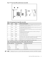
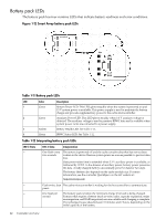
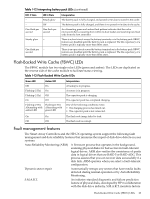
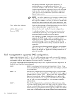
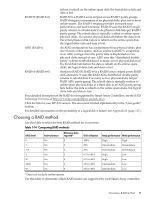
Table 1-12 Interpreting battery pack LEDs (continued) LED 3 State -- -- One flash per second LED 4 State Steady glow Off One flash per second Steady glow -- One flash per -second Interpretation The battery pack is fully charged, and posted write data is stored in the cache. The battery pack is fully charged, and there is no posted write data in the cache. An alternating green and amber flash pattern indicates that the cache microcontroller is executing from within its boot loader and receiving new flash code from the host controller. There is a short circuit across the battery terminals or in the battery pack. BBWC features are disabled until the battery pack is replaced. The life expectancy of a battery pack is typically more than three years. There is an open circuit across the battery terminals or in the battery pack. BBWC features are disabled until the battery pack is replaced. The life expectancy of a battery pack is typically more than three years. Flash-Backed Write Cache (FBWC) LEDs The FBWC module has two single-color LEDs (green and amber). The LEDs are duplicated on the reverse side of the cache module to facilitate status viewing. Table 1-13 Flash-Backed Write Cache LEDs Green LED Amber LED Off On Flashing (1 Hz) On Flashing (1 Hz) Off On Off Flashing (2 Hz) Flashing (2 Hz) Alternating with Alternating with amber LED green LED Interpretation A backup is in progress. A restore is in progress. The capacitor pack is charging. The capacitor pack has completed charging. One of the following conditions exists: • The charging process has timed out. • The capacitor pack is not connected. On On Off Off The flash code image failed to load. The flash code is corrupt. Fault management features The Smart Array Controllers and the HP-UX operating system support the following fault management and data reliability features that minimize the impact of disk drive defects on your systems: Auto-Reliability Monitoring (ARM) A firmware process that operates in the background, scanning physical disks for bad sectors in fault-tolerant logical drives. ARM also verifies the consistency of parity data in logical drives that use RAID 5 or RAID ADG. This process assures that you can recover data successfully if a disk fails. ARM operates when you select a fault-tolerant configuration. Dynamic sector repair Automatically remaps any sectors that have media faults detected during normal operation or by Auto-Reliability Monitoring. S.M.A.R.T. An industry-standard diagnostic and failure prediction feature of physical disks, developed by HP in collaboration with the disk drive industry. S.M.A.R.T. monitors factors Flash-Backed Write Cache (FBWC) LEDs 23
-
 1
1 -
2
-
3
-
4
-
5
-
6
-
7
-
8
-
9
-
10
-
11
-
12
-
13
-
14
-
15
-
16
-
17
-
 18
18 -
 19
19 -
 20
20 -
 21
21 -
 22
22 -
 23
23 -
 24
24 -
 25
25 -
 26
26 -
 27
27 -
 28
28 -
29
-
30
-
31
-
32
-
33
-
34
-
35
-
36
-
37
-
38
-
39
-
40
-
41
-
42
-
43
-
44
-
45
-
46
-
47
-
48
-
49
-
50
-
51
-
52
-
53
-
54
-
55
-
56
-
57
-
58
-
59
-
60
-
61
-
62
-
63
-
64
-
65
-
66
-
67
-
68
-
69
-
70
-
71
-
72
-
73
-
74
-
75
-
76
-
77
-
78
-
79
-
80
-
81
-
82
-
83
-
84
-
85
-
86
-
87
-
88
-
89
-
90
-
91
-
92
-
93
-
94
-
95
-
96
-
97
-
98
-
99
-
100
-
101
-
102
-
103
-
104
-
105
-
106
-
107
-
108
-
109
-
110
-
111
-
112
-
113
-
114
-
115
-
116
-
117
-
118
-
119
-
120
-
121
-
122
-
123
-
124
-
125
-
126
-
127
-
128
-
129
-
130
-
131
-
132
-
133
-
134
-
135
-
136
-
137
-
138
-
139
-
140
-
141
-
142
 |
 |