HP StorageWorks 300 HP StorageWorks 300 Virtual Library System user guide (AH1 - Page 120
Description, Status, SATA hard drive LED functionality is not currently supported.
 |
View all HP StorageWorks 300 manuals
Add to My Manuals
Save this manual to your list of manuals |
Page 120 highlights
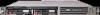
Item 1 Description Power On/Standby button and system power LED Status • Green = System is on. • Amber = System is shut down, but power is still applied. • Off = Power cord is not attached, power supply failure has occurred, no power supplies are installed, facility power is not available, or the DC-to-DC converter is not installed. 2 UID button/LED • Blue = Identification is activated. • Flashing blue = System is being managed remotely. • Off = Identification is deactivated. 3 Internal health LED • Green = System health is normal. • Amber = System is degraded. To identify the component in a degraded state, refer to system board LEDs. • Red = System is critical. To identify the component in a critical state, refer to system board LEDs. • Off = System health is normal (when in standby mode). 4 External health LED (power supply) 5 NIC 1 link/activity LED • Green = Power supply health is normal. • Amber = Power redundancy failure occurred. • Off = Power redundancy failure has occurred. When the node is in standby mode, power supply health is normal. • Green = Network link exists. • Flashing green = Network link and activity exist. • Off = No link to network exists. If power is off, view the LEDs on the RJ-45 connector for status by referring to the rear panel LEDs. 6 NIC 2 link/activity LED • Green = Network link exists. • Flashing green = Network link and activity exist. • Off = No link to network exists. If power is off, the front panel LED is not active. View the LEDs on the RJ-45 connector for status by referring to the rear panel LEDs. NOTE: SATA hard drive LED functionality is not currently supported. 120 Component identification
-
 1
1 -
2
-
3
-
4
-
5
-
6
-
7
-
8
-
9
-
10
-
11
-
12
-
13
-
14
-
15
-
16
-
17
-
18
-
19
-
20
-
21
-
22
-
23
-
24
-
25
-
26
-
27
-
28
-
29
-
30
-
31
-
32
-
33
-
34
-
35
-
36
-
37
-
38
-
39
-
40
-
41
-
42
-
43
-
44
-
45
-
46
-
47
-
48
-
49
-
50
-
51
-
52
-
53
-
54
-
55
-
56
-
57
-
58
-
59
-
60
-
61
-
62
-
63
-
64
-
65
-
66
-
67
-
68
-
69
-
70
-
71
-
72
-
73
-
74
-
75
-
76
-
77
-
78
-
79
-
80
-
81
-
82
-
83
-
84
-
85
-
86
-
87
-
88
-
89
-
90
-
91
-
92
-
93
-
94
-
95
-
96
-
97
-
98
-
99
-
100
-
101
-
102
-
103
-
104
-
105
-
106
-
107
-
108
-
109
-
110
-
111
-
112
-
113
-
114
-
 115
115 -
 116
116 -
 117
117 -
 118
118 -
 119
119 -
 120
120 -
 121
121 -
 122
122 -
 123
123 -
 124
124 -
 125
125 -
126
-
127
-
128
-
129
-
130
-
131
-
132
-
133
-
134
-
135
-
136
-
137
-
138
-
139
-
140
-
141
-
142
-
143
-
144
-
145
-
146
-
147
-
148
-
149
-
150
-
151
-
152
-
153
-
154
-
155
-
156
-
157
-
158
-
159
-
160
-
161
-
162
-
163
-
164
-
165
-
166
-
167
-
168
-
169
-
170
-
171
-
172
-
173
-
174
-
175
-
176
-
177
-
178
-
179
-
180
 |
 |
