HP StorageWorks 300 HP StorageWorks 300 Virtual Library System user guide (AH1 - Page 16
Components, System status monitoring, Redundancy
 |
View all HP StorageWorks 300 manuals
Add to My Manuals
Save this manual to your list of manuals |
Page 16 highlights
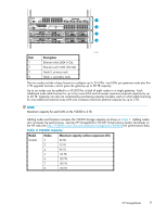
System status monitoring VLS hardware, environmental, and virtual device (library, tape drive, cartridge) status is constantly monitored by the VLS software and displayed on the VLS web user interface, Command View VLS. A notification alert is generated by the VLS software when a hardware or environmental failure is detected or predicted. VLS notification alerts are displayed on Command View VLS, and can also be sent as mail to the mail addresses you specify and/or SNMP traps to the management consoles you specify. For more information about viewing VLS hardware status, and/or receiving VLS notification alerts by mail or as SNMP traps, see Monitoring. Redundancy The VLS includes some important redundancy features: • Redundant fans Each node includes redundant fans. If a fan fails in a node (head unit), the remaining fans run at a faster speed, temporarily providing enough cooling. • Redundant power supply Each node includes a redundant power supply. With redundant power supplies, if one power supply fails in a node, the remaining functional power supply provides enough power for the node to function. HP recommends that the primary power supplies be connected to a separate power source at the site from the redundant power supplies. CAUTION: Replace a failed fan or power supply as soon as possible to maximize the life expectancy of the remaining fan(s) or power supply and to maintain redundancy. • Redundant system disks Each VLS node (head unit) contains two system hard drives configured into a RAID 1 (mirrored) volume. This provides dual boot capability and quick recovery if one of the system hard drives fail. For more information about VLS features, visit the HP web site: http://www.hp.com Components A VLS300 consists of at least two nodes (one primary node and between one and seven secondary nodes) and dual LAN switches for internal inter-node connections. See the drawing of racked nodes below. Each node contains dual processors, two dual port FC HBAs, four 512 MB memory modules, and two 80 Gb hard drives. No external storage is included with the VLS300; instead, the gateway uses external storage in existing arrays. 16 Introduction
-
 1
1 -
2
-
3
-
4
-
5
-
6
-
7
-
8
-
9
-
10
-
 11
11 -
 12
12 -
 13
13 -
 14
14 -
 15
15 -
 16
16 -
 17
17 -
 18
18 -
 19
19 -
 20
20 -
 21
21 -
22
-
23
-
24
-
25
-
26
-
27
-
28
-
29
-
30
-
31
-
32
-
33
-
34
-
35
-
36
-
37
-
38
-
39
-
40
-
41
-
42
-
43
-
44
-
45
-
46
-
47
-
48
-
49
-
50
-
51
-
52
-
53
-
54
-
55
-
56
-
57
-
58
-
59
-
60
-
61
-
62
-
63
-
64
-
65
-
66
-
67
-
68
-
69
-
70
-
71
-
72
-
73
-
74
-
75
-
76
-
77
-
78
-
79
-
80
-
81
-
82
-
83
-
84
-
85
-
86
-
87
-
88
-
89
-
90
-
91
-
92
-
93
-
94
-
95
-
96
-
97
-
98
-
99
-
100
-
101
-
102
-
103
-
104
-
105
-
106
-
107
-
108
-
109
-
110
-
111
-
112
-
113
-
114
-
115
-
116
-
117
-
118
-
119
-
120
-
121
-
122
-
123
-
124
-
125
-
126
-
127
-
128
-
129
-
130
-
131
-
132
-
133
-
134
-
135
-
136
-
137
-
138
-
139
-
140
-
141
-
142
-
143
-
144
-
145
-
146
-
147
-
148
-
149
-
150
-
151
-
152
-
153
-
154
-
155
-
156
-
157
-
158
-
159
-
160
-
161
-
162
-
163
-
164
-
165
-
166
-
167
-
168
-
169
-
170
-
171
-
172
-
173
-
174
-
175
-
176
-
177
-
178
-
179
-
180
 |
 |
