Honeywell HPF24S8 Installation Instructions
Honeywell HPF24S8 Manual
 |
View all Honeywell HPF24S8 manuals
Add to My Manuals
Save this manual to your list of manuals |
Honeywell HPF24S8 manual content summary:
- Honeywell HPF24S8 | Installation Instructions - Page 1
HPF24S6 & HPF24S8, HPF24S6E & HPF24S8E, HPF24S6C & HPF24S8C FIELD CHARGER/POWER SUPPLY INSTALLATION MANUAL P/N 52751:D3 • ECN 10-282 • 5/11/2010 - Honeywell HPF24S8 | Installation Instructions - Page 2
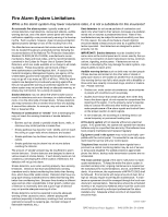
Maintenance should be scheduled monthly or as required by National and/or local fire codes and should be performed by authorized professional fire alarm installers only. Adequate written records of all inspections should be kept. Limit-C1-2-2007 HPF24S Series Power Supplies - P/N 52751:D3 5/11/2010 - Honeywell HPF24S8 | Installation Instructions - Page 3
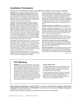
Services Department if any problems are anticipated or encountered. Disconnect AC power and batteries installed and used in accordance with the instruction manual Honeywell International Inc. All rights reserved. Unauthorized use of this document is strictly prohibited. HPF24S Series Power Supplies - Honeywell HPF24S8 | Installation Instructions - Page 4
for how to correct/improve documentation Send email messages to: [email protected] Please note this email address is for documentation feedback only. If you have any technical issues, please contact Technical Services. 4 HPF24S Series Power Supplies - P/N 52751:D3 5/11/2010 - Honeywell HPF24S8 | Installation Instructions - Page 5
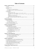
and 7 (+) & 8 (-) alarm polarity...12 Trouble Relay Contact Rating: TB5...12 Secondary Power (battery) Charging Circuit: JP4 12 Special Application Auxiliary Power Output: TB4 Terminals 9 (+) & 10 12 1.7: General...14 Section 2: Installation...15 2.1: Backbox Mounting ...15 2.2: NAC Circuit Wiring - Honeywell HPF24S8 | Installation Instructions - Page 6
How to Calculate System Current Draw 39 6.4: Calculating the Battery Size...40 6.4.1: NFPA Battery Requirements ...41 6.4.2: Selecting and Locating Batteries ...41 Appendix 46 System Sensor...46 Gentex...46 Cooper-Wheelock ...47 Index ...48 6 HPF24S Series Power Supplies - P/N 52751:D3 5/11/2010 - Honeywell HPF24S8 | Installation Instructions - Page 7
for Hearing Impaired CAN/ULC - S524-01 Standard for Installation of Fire Alarm Systems CAN/ULC-S527-99 Standard for Control LAHJ) Canadian Electrical Code, Part 1 Other Honeywell Documents: Device Compatibility Document Document #51939 This Series Power Supplies - P/N 52751:D3 5/11/2010 7 - Honeywell HPF24S8 | Installation Instructions - Page 8
8 HPF24S Series Power Supplies - P/N 52751:D3 5/11/2010 - Honeywell HPF24S8 | Installation Instructions - Page 9
features as the HPF24S6 and HPF24S8 respectively. Unless otherwise specified, the information in this manual also applies to the Canadian versions of the power supplies. 1.1 General The HPF24S power supplies can be used as remotely mounted power supplies and battery chargers to power four noncoded - Honeywell HPF24S8 | Installation Instructions - Page 10
current (one hour maximum): - 6.0 amps for HPF24S6 - 8.0 amps for HPF24S8 • Integral supervised battery charger for lead acid batteries only • Capable of charging 7.0 AH to 18.0 AH (Amp Hour) batteries • Fully supervised power supply, battery and NACs • Selectable Strobe Synchronization for NACs - Honeywell HPF24S8 | Installation Instructions - Page 11
power supply battery is connected and the charger develops a problem, only the Charger Trouble/AC Loss LED will turn on. 1.6 Specifications Refer to Figure 1.1 on page 13 for terminal locations. Primary AC Power - TB1 • HPF24S6 & HPF24S8: 120 VAC, 60 Hz, 3.2 amps maximum • HPF24S6E & HPF24S8E - Honeywell HPF24S8 | Installation Instructions - Page 12
, nonpower-limited • Supports lead acid type batteries only • Float Charge Voltage: 27.6 VDC • Maximum Charge Current: 1.5 A • Battery fuse (F1) 15A, 30V (Candadian version is nonreplaceable 12A, 32V) • Maximum Battery Capacity: 18.0 AH • Minimum Battery Capacity: 7.0 AH • Power supply draws maximum - Honeywell HPF24S8 | Installation Instructions - Page 13
500 mA Special Application Power LEDs Charger Trouble/AC Loss (yellow) NAC Trouble (yellow) Battery Trouble (yellow) Ground Fault (yellow) AC Power (green) SW1 Programming FACP connected to the power supply. Cut jumper JP1 only if a panel connected to the power supply is monitoring for Ground - Honeywell HPF24S8 | Installation Instructions - Page 14
is disabled and the circuits are no longer supervised. Supervision of other power supply faults such as low battery, battery charger trouble, ground fault and AC loss will continue and may be monitored via the power supply trouble relay. If an application requires that all four outputs activate at - Honeywell HPF24S8 | Installation Instructions - Page 15
, vibration-free area where extreme temperatures are not encountered. The area should be readily accessible with sufficient room to easily install and maintain the power supply. Locate the top of the cabinet approximately five feet above the floor with the hinge mounting on the left. Determine the - Honeywell HPF24S8 | Installation Instructions - Page 16
Installation Backbox Mounting 2.875" (7.3 cm) 0.75" (1.9 cm) Height=15.00" (38.10 cm) 10.625" (26.99 cm) Top Backbox = Pem Studs Backbox Mounting Holes Bottom 1.125" (2.868 cm) Figure 2.2 Backbox Mounting Dimensions rcpscabb.wmf 16 HPF24S Series Power Supplies - P/N 52751:D3 5/11/2010 - Honeywell HPF24S8 | Installation Instructions - Page 17
Wiring Installation HPF24S6 or HPF24S8 to support Style Z (Class A) Notification Appliance Circuits. ZNAC-4 Option Module ZNAC-4 Horn Strobes Alarm Polarity Shown 24fsclsa.cdr J3 HPF24S Circuit Board Figure 2.4 Style Z (Class A) NACs using ZNAC-4 Option Module HPF24S Series Power Supplies - Honeywell HPF24S8 | Installation Instructions - Page 18
11 (-) and 10 (+). NOTE: The module mounting kit (P/N 90286) is pre-installed on the power supply main circuit board. *If the SLC device does not match the one in this figure, refer to the SLC manual appendix, which contains wiring conversion charts for type V and type H modules. 24fsmodltpH - Honeywell HPF24S8 | Installation Instructions - Page 19
-limited Circuits *If the SLC device does not match the one in this figure, refer to the SLC manual appendix, which contains wiring conversion charts for type V and type H modules. Figure 2.6 Power-limited Wiring Example 24fspwrltpH.wmf HPF24S Series Power Supplies - P/N 52751:D3 5/11/2010 19 - Honeywell HPF24S8 | Installation Instructions - Page 20
positions. Important: Change DIP switch settings only when all power (AC and DC) is removed. 24fsswitc.wmf Switches 1 through 7 shown in OFF (Open) position Switch 8 shown in ON (Closed) position Figure 3.1 Field Programming DIP Switches 20 HPF24S Series Power Supplies - P/N 52751:D3 5/11/2010 - Honeywell HPF24S8 | Installation Instructions - Page 21
Trouble Relay responds to all troubles. Aux. Trouble Relay responds only to AC Fail/brownout. Internal trouble contact responds to AC loss Internal trouble without turning off the strobe. 5 When using Split Alarm with power supply configured in Slave Mode, System Sensor can not be used (Use - Honeywell HPF24S8 | Installation Instructions - Page 22
Sensor Wheelock Gentex HPF24S6 (max. strobes) 51 30 39 HPF24S8 (max. strobes) 51 40 39 3.2.2 Synchronization Mode - Master/Slave The HPF24S power supply can be configured for Master or Slave Synchronization by setting DIP switch 3 ON for Slave or OFF for Master mode. In some installations, it is - Honeywell HPF24S8 | Installation Instructions - Page 23
. • DIP switch 4 set to the ON position will delay the generation of an AC Loss/brownout trouble signal for 2 hours. In addition, the Aux. Trouble Relay will immediately respond to all trouble conditions on the power supply. • DIP switch 4 set to the OFF position will allow the HPF24S to generate - Honeywell HPF24S8 | Installation Instructions - Page 24
device without turning off the strobe. 4 When using Split Alarm with power supply configured in Slave Mode, System Sensor can not be used (Use position will disable the charger. It should only be disabled if an external battery charger is being used for the HPF24S. 3.2.6 Door Closers Output Circuit - Honeywell HPF24S8 | Installation Instructions - Page 25
not respond to an AC Fail condition.) • A battery fail condition at the power supply • A battery charger fail on the power supply • A ground fault condition on the power supply (zero impedance between the power supply and ground) Any power supply trouble will break the connection between the FACP - Honeywell HPF24S8 | Installation Instructions - Page 26
conditions will cause the normally energized trouble relay to change states regardless of whether the panel is in alarm or standby: - An AC fail condition at the power supply - A battery fail condition at the power supply - A battery charger fail on the power supply - A ground fault condition on the - Honeywell HPF24S8 | Installation Instructions - Page 27
Notes HPF24S Series Power Supplies - P/N 52751:D3 5/11/2010 27 - Honeywell HPF24S8 | Installation Instructions - Page 28
5.1 Controlling Four NACs With One Input and Selective Silence NOTE: The Relay Module is required only for this application with the power supply set as Master. If the power supply is set as Slave, the Relay Module is not required. In Slave mode, selective silence (horn mute) is provided by the - Honeywell HPF24S8 | Installation Instructions - Page 29
SLC manual appendix, which contains wiring conversion charts for type V and type H modules. Figure 5.1 Controlling Four Outputs With One Input Notes: The following notes apply to Figure 5.1 on page 29. 1. When the HPF24S power supply is in an inactive state (control module not active), a trouble - Honeywell HPF24S8 | Installation Instructions - Page 30
installed between TB4, Terminals 5 & 6 for control module wiring supervision (the ELR value is dependent on the module employed). 5. Supervise the power NACs and One Door Holder With One Input In this application, the power supply has been set as a master with synchronized outputs. All four HPF24S - Honeywell HPF24S8 | Installation Instructions - Page 31
figure, refer to the SLC manual appendix, which contains wiring trouble contacts at TB5 of the power supply can also be used for independent trouble monitoring. 3. Do not loop wires under screw terminals. Break wires to maintain proper supervision. 4. An End-of-Line Resistor must be installed - Honeywell HPF24S8 | Installation Instructions - Page 32
is used to activate the power supply's temporal output circuits 3 & 4. Note: All NACs are supervised and power-limited ELR not required for Style Z (Class A) NAC Bells Use listed ELR (4.7K) to terminate Style Y (Class B) NAC Bells Style Z (Class A) Internal Trouble Contact HPF24S End-of-Line - Honeywell HPF24S8 | Installation Instructions - Page 33
5 & 6). As an alternative, the trouble contacts at TB5 of the power supply can also be used for independent trouble monitoring. 2. Do not loop wires under screw terminals. Break wires to maintain proper supervision. 3. An End-of-Line Resistor must be installed between terminals 5 & 6 for control - Honeywell HPF24S8 | Installation Instructions - Page 34
Alarm 7 = OFF (charger enabled) 8 = OFF (circuit 4 NAC) Figure 5.4 Remote Power Supply Application Notes: The following notes apply to Figure 5.4 on page 34. 1. An End-of-Line Resistor must be installed between TB5, Terminal 1 (trouble relay common) and the monitor module input circuit for - Honeywell HPF24S8 | Installation Instructions - Page 35
Power Supply Applications 5.5 Master FACP With Slave HPF24S Power Supply In this application, an HPF24S power supply, configured as a Slave unit, is connected to a master FACP NAC programmed for synchronized output. The power supply . Refer to the FACP user manual to determine the source of the - Honeywell HPF24S8 | Installation Instructions - Page 36
Applications Master HPF24S Power Supply Connected to FACP 5.6 Master HPF24S Power Supply Connected to FACP In this application, a master HPF24S power supply, set for synchronization, is connected to an FACP NAC with no synchronized output. Standby Polarity Shown 24fsapp11.cdr HPF24S Horn/ - Honeywell HPF24S8 | Installation Instructions - Page 37
terminal of the host FACP. NAC Outputs only Cut JP1 24fsCanadiantpH.wmf Battery - Battery - HPF24S Power Supply *If the SLC device does not match the one in this figure, refer to the SLC manual appendix, which contains wiring conversion charts for type V and type H modules. Host FACP HPF24S - Honeywell HPF24S8 | Installation Instructions - Page 38
fire alarm conditions and calculating the secondary (battery) load 3. Calculating the size of batteries required to support the system if an AC power loss occurs 4. Selecting the proper batteries for your system 6.2 Calculating the AC Branch Circuit The power supply requires connection to a separate - Honeywell HPF24S8 | Installation Instructions - Page 39
the power supply must support during a non-fire alarm condition, with AC power applied - Calculation Column 2 - The primary supply current load the power supply must support during a fire alarm condition, with AC power applied - Calculation Column 3 - The standby current drawn from the batteries in - Honeywell HPF24S8 | Installation Instructions - Page 40
load in ampere hours (AH). This total load determines the battery size (in AH) required to support the power supply under the loss of AC power. Complete Table 6.4 as follows: 1. Enter the totals from Table 6.3 on page 40, Calculation Columns 2 and 3 where shown. 2. Enter the NFPA Standby and Alarm - Honeywell HPF24S8 | Installation Instructions - Page 41
alarm 6.4.2 Selecting and Locating Batteries Select batteries that meet or exceed the total ampere hours calculated in Table 6.4 . The power supply can charge batteries in the 7 AH to 18 AH range. The power supply cabinet is capable of housing batteries up to 7 AH. Batteries larger than 7 AH require - Honeywell HPF24S8 | Installation Instructions - Page 42
each circuit. The following table lists NAC wiring requirements for the HPF24S6 and HPF24S8 Field Charger Power Supply. NAC Load (Amps) 0.25 0.5 0.75 1.0 1.25 138 87 55 34 Table A.1 NAC Wiring Requirements for Power Supply Calculations are based on Direct-Current Resistance data for uncoated - Honeywell HPF24S8 | Installation Instructions - Page 43
, PC2RH, PC2WH, PC4R, PC4W, PC4RH, PC4WH, SCR, SCW, SCRH, SCWH, SR, SW, SRH, SWH, SW-ALERT, SWH-ALERT, MHR,MHW followed by suffixes HPF24S Series Power Supplies - P/N 52751:D3 5/11/2010 43 - Honeywell HPF24S8 | Installation Instructions - Page 44
, ST24-30, ST24-60, ST24-110, ST24-75W,ST24-110W, ST24-30W Strobe WGMS-24-75 Weatherproof Electro-Mechanical Horn with Strobe 44 HPF24S Series Power Supplies - P/N 52751:D3 5/11/2010 - Honeywell HPF24S8 | Installation Instructions - Page 45
-24-VFR, MS3-24-VFR Strobe MSP-24-HFR Strobe MT-12/24-R MultiTone MT-24-WM, MT-24-WM-VFR MultiTone Strobe117cd HPF24S Series Power Supplies - P/N 52751:D3 5/11/2010 45 - Honeywell HPF24S8 | Installation Instructions - Page 46
24R/W A.1.4 Notification Appliances For Canadian Applications • Refer to manufacturer's installation instructions for more information. • Contact manufacturer for current draws or additional options color). Intended for indoor use on a wall. 46 HPF24S Series Power Supplies - P/N 52751:D3 5/11/2010 - Honeywell HPF24S8 | Installation Instructions - Page 47
-FW, RSS-24100-CR-FW, RSS-24150-CR-FW, RSS-24177-CR-FW, RSS-24MCC-FR/W, RSS24MCW-FR/W, RSSP-24MCW-FR/W, RSSP-241575W HPF24S Series Power Supplies - P/N 52751:D3 5/11/2010 47 - Honeywell HPF24S8 | Installation Instructions - Page 48
25 End-of-Line Resistor see also ELR 25 F faults 25 Features 9 filtered power 9 float charge voltage 12 Form-C see also Relay 10 G Gentex - 24VDC 44 ground fault 9 ground fault detection 10, 11 Jumper JP1 11 ground fault LED 11 H HPF24S6 9 48 HPF24S Series Power Supplies - P/N 52751:D3 5/11/2010 - Honeywell HPF24S8 | Installation Instructions - Page 49
and jumpers 13 power supply requirements 38 powering supply 38 power-limited 9 power-limited wiring 19 R relay trouble 9, 10, 12, 25 reporting delay AC loss 26 resettable power 24 S secondary power see also battery 12 Specific Application Power see also Auxiliary Power 12 specifications 11 - Honeywell HPF24S8 | Installation Instructions - Page 50
System Sensor - 24VDC 43 T trouble supervision 25 trouble relay 9, 10, 12, 25 contact rating 12 trouble supervision 9 troubles 25 power supply 9 W wiring 10 AC power 12 power-limited 19 Z ZNAC-4 17 see also Class A Converter Module 9 Index 50 HPF24S Series Power Supplies - P/N 52751:D3 5/11/2010 - Honeywell HPF24S8 | Installation Instructions - Page 51
HPF24S Series Power Supplies - P/N 52751:D3 5/11/2010 51 - Honeywell HPF24S8 | Installation Instructions - Page 52
Automation and Control Solutions Honeywell Power Products l2 Clintonville Road Northford, CT 06472-1610 www.honeywellpower.com ® U.S. Registered Trademark © 2010 Honeywell International Inc. 52751 D3. Rev. 05-10
-
 1
1 -
 2
2 -
 3
3 -
 4
4 -
 5
5 -
 6
6 -
 7
7 -
8
-
9
-
10
-
11
-
12
-
13
-
14
-
15
-
16
-
17
-
18
-
19
-
20
-
21
-
22
-
23
-
24
-
25
-
26
-
27
-
28
-
29
-
30
-
31
-
32
-
33
-
34
-
35
-
36
-
37
-
38
-
39
-
40
-
41
-
42
-
43
-
44
-
45
-
46
-
47
-
48
-
49
-
50
-
51
-
52
 |
 |

INSTALLATION MANUAL
HPF24S6 & HPF24S8, HPF24S6E &
HPF24S8E, HPF24S6C & HPF24S8C
FIELD CHARGER/POWER SUPPLY
P/N 52751:D3 • ECN 10-282 • 5/11/2010