Honeywell HPF24S8 Installation Instructions - Page 20
Programming Options
 |
View all Honeywell HPF24S8 manuals
Add to My Manuals
Save this manual to your list of manuals |
Page 20 highlights
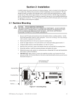
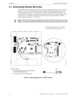
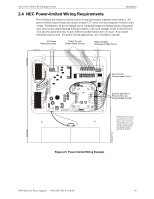
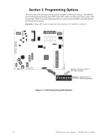
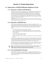
Section 3: Programming Options This section describes the programming options available via DIP switch settings. The HPF24S can be field programmed using option DIP switch SW1 which is located in the lower center of the circuit board. Refer to the following illustration for switch location and DIP switch placement in the ON and OFF positions. Important: Change DIP switch settings only when all power (AC and DC) is removed. 24fsswitc.wmf Switches 1 through 7 shown in OFF (Open) position Switch 8 shown in ON (Closed) position Figure 3.1 Field Programming DIP Switches 20 HPF24S Series Power Supplies - P/N 52751:D3 5/11/2010
-
 1
1 -
2
-
3
-
4
-
5
-
6
-
7
-
8
-
9
-
10
-
11
-
12
-
13
-
14
-
 15
15 -
 16
16 -
 17
17 -
 18
18 -
 19
19 -
 20
20 -
 21
21 -
 22
22 -
 23
23 -
 24
24 -
 25
25 -
26
-
27
-
28
-
29
-
30
-
31
-
32
-
33
-
34
-
35
-
36
-
37
-
38
-
39
-
40
-
41
-
42
-
43
-
44
-
45
-
46
-
47
-
48
-
49
-
50
-
51
-
52
 |
 |

20
HPF24S Series Power Supplies —
P/N 52751:D3
5/11/2010
Section 3: Programming Options
This section describes the programming options available via DIP switch settings.
The HPF24S
can be field programmed using option DIP switch SW1 which is located in the lower center of the
circuit board.
Refer to the following illustration for switch location and DIP switch placement in
the ON and OFF positions.
Important
: Change DIP switch settings only when all power (AC and DC) is removed
.
Figure 3.1
Field Programming DIP Switches
Switches 1 through 7 shown in
OFF (Open) position
Switch 8 shown in
ON (Closed) position
24fsswitc.wmf