Honeywell HPF24S8 Installation Instructions - Page 48
Index
 |
View all Honeywell HPF24S8 manuals
Add to My Manuals
Save this manual to your list of manuals |
Page 48 highlights
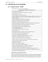
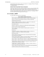
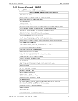
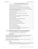
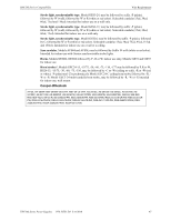
Index A AC Loss 9 Loss Reporting Delay 26 AC fail delay 23 see also AC loss reporting delay 23 AC loss reporting delay 23 AC loss reporting delay 10 AC power 11 current 11 LED 11 voltage 11 activation reverse polarity 9 alarm condition 9 applications 9 Auxiliary Power 10, 12 current 12 voltage 12 Auxiliary Power Control see also resettable or nonresettable power 24 B backbox dimensions 16 battery capacity 12 charge current 12 charger capacity 10 float charge voltage 12 fuse F1 12 lead acid 10, 12 maximum capacity 10 see also secondary power 12 trouble 9 battery/charger trouble LED 11 C cabinet see also backbox 16 capacity battery 12 charge current maximum 12 charger trouble 9 LED 11 circuit board layout 13 Class A Converter Module 17 see also ZNAC-4 9 Class B see also Style Y 9 Coded Input 11 Coded/Noncoded Input Selection 11 coding NAC 9 compatibility input circuit 9 control circuit 9 current 12 see also input circuit 12 voltage 12 current maximum continuous 9 maximum short term 10 standby 12 total continuous 12 total short term 12 D Device Compatibility 43 dimensions backbox 16 E ELR installation 25 see also End-of-Line Resistor 25 End-of-Line Resistor see also ELR 25 F faults 25 Features 9 filtered power 9 float charge voltage 12 Form-C see also Relay 10 G Gentex - 24VDC 44 ground fault 9 ground fault detection 10, 11 Jumper JP1 11 ground fault LED 11 H HPF24S6 9 48 HPF24S Series Power Supplies - P/N 52751:D3 5/11/2010
-
 1
1 -
2
-
3
-
4
-
5
-
6
-
7
-
8
-
9
-
10
-
11
-
12
-
13
-
14
-
15
-
16
-
17
-
18
-
19
-
20
-
21
-
22
-
23
-
24
-
25
-
26
-
27
-
28
-
29
-
30
-
31
-
32
-
33
-
34
-
35
-
36
-
37
-
38
-
39
-
40
-
41
-
42
-
 43
43 -
 44
44 -
 45
45 -
 46
46 -
 47
47 -
 48
48 -
 49
49 -
 50
50 -
 51
51 -
 52
52
 |
 |
