Honeywell HPF24S8 Installation Instructions - Page 32
Split Temporal Mode of Operation
 |
View all Honeywell HPF24S8 manuals
Add to My Manuals
Save this manual to your list of manuals |
Page 32 highlights
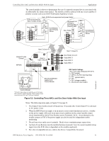
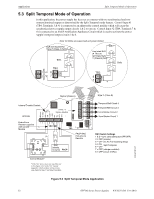
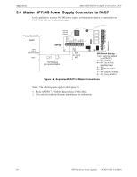
Applications Split Temporal Mode of Operation 5.3 Split Temporal Mode of Operation In this application, the power supply has been set as a master with two synchronized and two nonsynchronized outputs as determined by the Split Temporal mode feature. Control Input #1 (TB4, Terminals 3 & 4) is connected to an addressable control module which will cause the synchronized power supply output circuits 1 & 2 to turn on. Control Input #2 (TB4, Terminals 7 & 8) is connected to an FACP Notification Appliance Circuit which is used to activate the power supply's temporal output circuits 3 & 4. Note: All NACs are supervised and power-limited ELR not required for Style Z (Class A) NAC Bells Use listed ELR (4.7K) to terminate Style Y (Class B) NAC Bells Style Z (Class A) Internal Trouble Contact HPF24S End-of-Line Resistor supplied with Control Module SLC ZNAC-4 Option Module NAC (steady, no sync) FACP FACP NAC End-of-Line Resistor Control Module* *If the SLC device does not match the one in this figure, refer to the SLC manual appendix, which contains wiring conversion charts for type V and type H modules. Style Y (Class B) Temporal Bell Circuit 4 Temporal Bell Circuit 3 Horn/Strobe Circuit 2 Horn/Strobe Circuit 1 SW1 Switch Settings 1 & 2 = sync (any setting but OFF/OFF) 3 = OFF (master) 4 = OFF (no AC Fail reporting delay) 5 = ON Split Temporal 6 = OFF 7 = OFF (charger enabled) 8 = OFF (circuit 4 NAC) Figure 5.3 Split Temporal Mode Application 24fsapp5tpH.wmf 32 HPF24S Series Power Supplies - P/N 52751:D3 5/11/2010
-
 1
1 -
2
-
3
-
4
-
5
-
6
-
7
-
8
-
9
-
10
-
11
-
12
-
13
-
14
-
15
-
16
-
17
-
18
-
19
-
20
-
21
-
22
-
23
-
24
-
25
-
26
-
 27
27 -
 28
28 -
 29
29 -
 30
30 -
 31
31 -
 32
32 -
 33
33 -
 34
34 -
 35
35 -
 36
36 -
 37
37 -
38
-
39
-
40
-
41
-
42
-
43
-
44
-
45
-
46
-
47
-
48
-
49
-
50
-
51
-
52
 |
 |
