Honeywell HPF24S8 Installation Instructions - Page 13
HPF24S Board Layout
 |
View all Honeywell HPF24S8 manuals
Add to My Manuals
Save this manual to your list of manuals |
Page 13 highlights
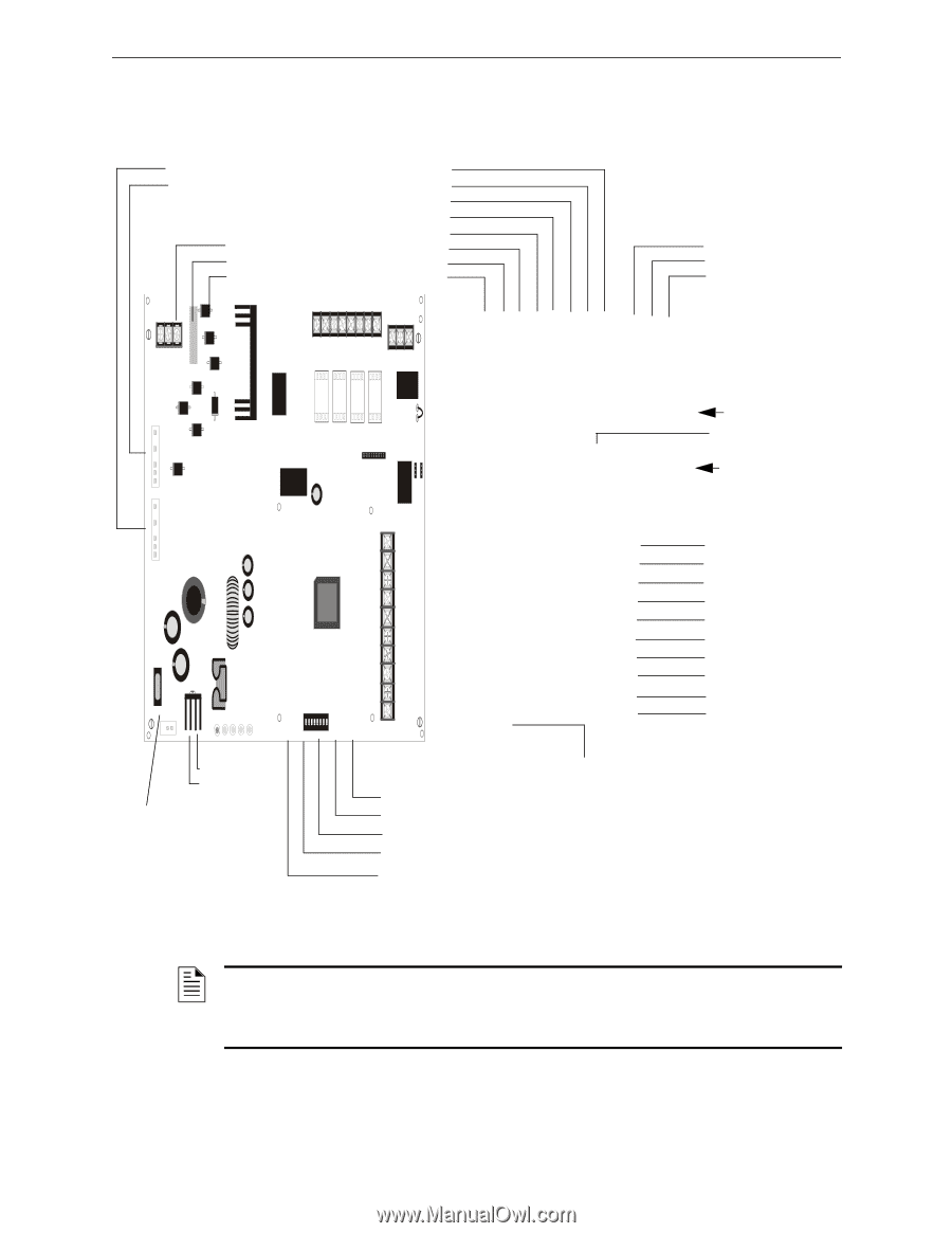
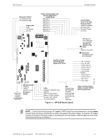
Specifications System Overview Nonpower-limited To Transformer #1 To Transformer #2 Supervised Earth AC Neutral AC Hot EARTH NEUT HOT TB1 Power-limited,Supervised, Special Application in NAC Mode NAC/Out 1 + NAC/Out 1 NAC/Out 2 + NAC/Out 2 NAC/Out 3 + NAC/Out 3 NAC/Out 4 + NAC/Out 4 - OUT4 OUT3 OUT2 OUT1 - NAC4 + - NAC3 + - NAC2 + - NAC1 + TB2 AUX TBL NO NC COM TB5 8 7 6 5 4 3 2 1 3 2 1 TRANSFORM ER 2 TRANSFORM ER 1 J2 J1 F1 - + JP4 AC GND FLT BATT NAC AC/ TRBL CHGR ON SW1 1 2 3 4 5 6 7 8 BATTERY JP4 Supervised + Battery - Battery 18 AH, 24 VDC F1 Nonpower- Battery Fuse 15A, 32V limited (Canadian version is nonreplaceable 12 A, 32V) JP1 J3 JP2 JP3 AUX - 10 AUX + 9 IN2- 8 IN2+ 7 OUT1- 6 OUT1+ 5 IN1- 4 IN1+ 3 SYNC IN - 2 SYNC IN + 1 TB4 Auxiliary Output 500 mA Special Application Power LEDs Charger Trouble/AC Loss (yellow) NAC Trouble (yellow) Battery Trouble (yellow) Ground Fault (yellow) AC Power (green) SW1 Programming DIP Switches (Change switch settings only when all power (AC and DC) is removed.) Figure 1.1 HPF24S Board Layout Trouble Relay Form-C Fail-safe Nonsupervised (shown energized) Normally Open Normally Closed Common JP1 Ground Fault Detection (cut to disable) see Note at bottom of the page. J3 ZNAC-4 Connector JP2 & JP3 Coded/Noncoded Input Selection - Aux. Common + Aux. 24 VDC* - Control Input 2 + Control Input 2 - Out Common + Out/Trouble Contact - Control Input 1 + Control Input 1 - Sync Input + Sync Input *Note: Auxiliary Power Output is power-limited but not supervised 24fs8brd.wmf NOTE: Cutting Ground Fault jumper JP1 voids UL/NFPA Style/Class identifications for circuits unless Ground Faults are being monitored by an FACP connected to the power supply. Cut jumper JP1 only if a panel connected to the power supply is monitoring for Ground Faults or with the approval of the local AHJ (Authority Having Jurisdiction). HPF24S Series Power Supplies - P/N 52751:D3 5/11/2010 13
-
 1
1 -
2
-
3
-
4
-
5
-
6
-
7
-
 8
8 -
 9
9 -
 10
10 -
 11
11 -
 12
12 -
 13
13 -
 14
14 -
 15
15 -
 16
16 -
 17
17 -
 18
18 -
19
-
20
-
21
-
22
-
23
-
24
-
25
-
26
-
27
-
28
-
29
-
30
-
31
-
32
-
33
-
34
-
35
-
36
-
37
-
38
-
39
-
40
-
41
-
42
-
43
-
44
-
45
-
46
-
47
-
48
-
49
-
50
-
51
-
52
 |
 |