Honeywell HPF24S8 Installation Instructions - Page 11
Jumpers, LED Indicators, Specifications - hpf24s8e
 |
View all Honeywell HPF24S8 manuals
Add to My Manuals
Save this manual to your list of manuals |
Page 11 highlights
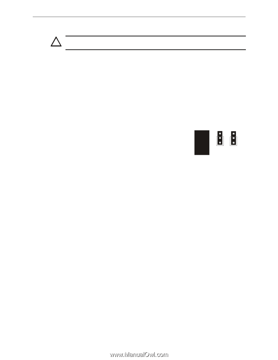
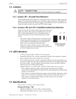
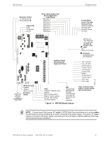
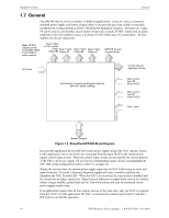
Jumpers 1.4 Jumpers System Overview ! CAUTION: DISCONNECT POWER REMOVE ALL POWER (AC & DC) BEFORE CUTTING OR MOVING ANY JUMPERS. 1.4.1 Jumper JP1 - Ground Fault Detection The Ground Detection circuit monitors for zero impedance between the power supply and ground. Jumper JP1 is located in the top right section of the power supply circuit board. Cutting JP1 will disable ground fault detection by the power supply. This should only be done if ground faults are being monitored by a panel connected to the HPF24S power supply. 24s8jp3b.wmf 1.4.2 Jumpers JP2 and JP3: Coded/Noncoded Input Selection Jumpers JP2 and JP3 are located in the top right section of the power supply circuit board. JP2 is used for Control Input Circuit #1 and JP3 is used for Control Input Circuit #2. The position of these jumpers will depend on the type of signal being fed to the input circuits: • If the source voltage to the input circuit is a noncoded (steady voltage) input signal, the jumper for the corresponding input circuit should be in the default position which jumpers the bottom two pins (as illustrated in drawing at left). • If the source voltage to the input circuit is coded (variable voltage), the jumper for the corresponding input circuit should be moved to jumper the top two pins. JP3 JP2 jumpers Jumper positions shown for noncoded (steady) source voltage 1.5 LED Indicators • AC Power on (green) LED - indicates AC power is present • Ground Fault (yellow) LED - indicates a ground fault condition (zero impedance to ground) • Battery Trouble (yellow) LED - indicates low or no battery • NAC Trouble (yellow) LED - indicates a Notification Appliance Circuit trouble (blinks once for Circuit 1 trouble, twice for Circuit 2 trouble, three times for Circuit 3 trouble and four times for Circuit 4 trouble. Note that multiple circuits in trouble will cause the LED to blink the number of the circuit with the highest number) • ChargerTrouble/AC Loss (yellow) LED - indicates a charger fault or loss of AC power - If AC is applied to the power supply without a battery connected, both the Charger Trouble/AC Loss LED and Battery Trouble LED will turn on simultaneously, indicating that a battery is not connected. - When a battery is connected and the power supply is in Normal Mode, if the battery voltage drops too low or the battery is disconnected, only the Battery Trouble LED will turn on. - When a battery is connected and the charger develops a problem, only the Charger Trouble/AC Loss LED will turn on. 1.6 Specifications Refer to Figure 1.1 on page 13 for terminal locations. Primary AC Power - TB1 • HPF24S6 & HPF24S8: 120 VAC, 60 Hz, 3.2 amps maximum • HPF24S6E & HPF24S8E: 240 VAC, 50 Hz, 1.6 amps maximum HPF24S Series Power Supplies - P/N 52751:D3 5/11/2010 11
-
 1
1 -
2
-
3
-
4
-
5
-
 6
6 -
 7
7 -
 8
8 -
 9
9 -
 10
10 -
 11
11 -
 12
12 -
 13
13 -
 14
14 -
 15
15 -
 16
16 -
17
-
18
-
19
-
20
-
21
-
22
-
23
-
24
-
25
-
26
-
27
-
28
-
29
-
30
-
31
-
32
-
33
-
34
-
35
-
36
-
37
-
38
-
39
-
40
-
41
-
42
-
43
-
44
-
45
-
46
-
47
-
48
-
49
-
50
-
51
-
52
 |
 |