Honeywell HPF24S8 Installation Instructions - Page 26
AC Loss Reporting Delay - hpf24s6 manual
 |
View all Honeywell HPF24S8 manuals
Add to My Manuals
Save this manual to your list of manuals |
Page 26 highlights
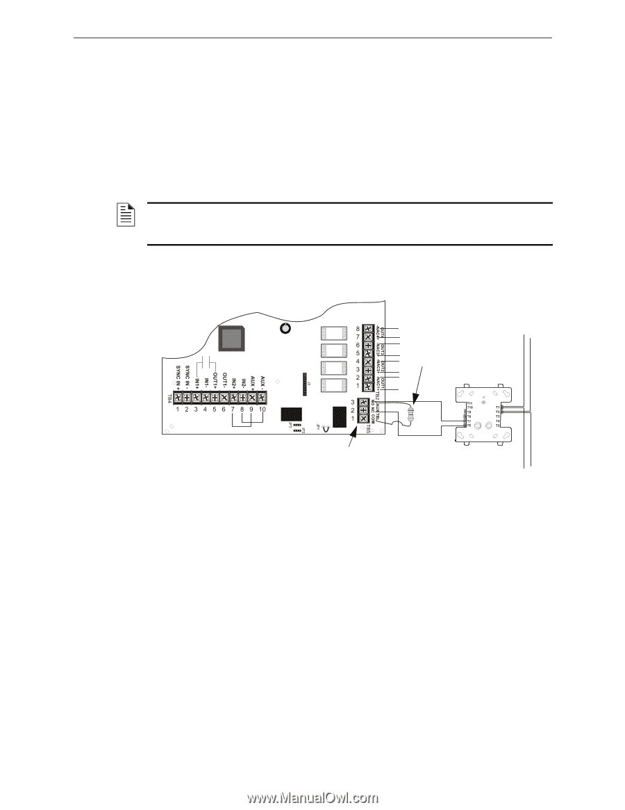
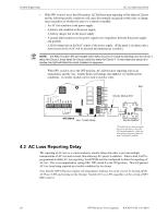
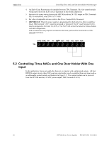
Trouble Supervision AC Loss Reporting Delay • With SW1 switch 4 set to the ON position, AC Fail/brownout reporting will be delayed 2 hours and the following trouble conditions will cause the normally energized trouble relay to change states regardless of whether the panel is in alarm or standby: - An AC fail condition at the power supply - A battery fail condition at the power supply - A battery charger fail on the power supply - A ground fault condition on the power supply (zero impedance between the power supply and ground) - A field wiring fault on the NAC output of the power supply. (If the panel is in alarm, only a short circuit on the NAC will be detected and indicated as a trouble). NOTE: the NAC Trouble LED will indicate which NAC circuit is in trouble by blinking once for Circuit 1, twice for Circuit 2, three times for Circuit 3 and four times for Circuit 4. If more than one circuit is in trouble, the LED will blink the circuit numbers in sequence. With SW1 switch 4 set to the OFF position, AC fail/brownout reporting will occur immediately and the Aux. Trouble Relay will change state only for AC fail/brownout conditions. A monitor module can be used to monitor relay. SLC Monitor Module ELR HPF24S6/8 Aux. Trouble Relay NO NC 7 6 Monitor Module* *If the SLC device does not match the one in this figure, refer to the SLC manual appendix, which contains wiring conversion charts for type V and type H modules. 4.2 AC Loss Reporting Delay The reporting of AC loss to a central station is usually delayed in order to prevent multiple transmissions of AC loss and restoral, thus allowing AC power to stabilize. When a host FACP is programmed to delay AC loss reporting, the HPF24S must be configured to delay the reporting of AC fail. This is accomplished by setting SW1 DIP switch 4 to the ON position. This will prevent AC loss from being reported as a trouble condition for two hours. Note that the HPF24S power supply will immediately indicate loss of AC power by turning off the AC Power LED and turning on the Charger Trouble/AC Loss LED, regardless of the setting of SW1 DIP switch 4. 26 HPF24S Series Power Supplies - P/N 52751:D3 5/11/2010
-
 1
1 -
2
-
3
-
4
-
5
-
6
-
7
-
8
-
9
-
10
-
11
-
12
-
13
-
14
-
15
-
16
-
17
-
18
-
19
-
20
-
 21
21 -
 22
22 -
 23
23 -
 24
24 -
 25
25 -
 26
26 -
 27
27 -
 28
28 -
 29
29 -
 30
30 -
 31
31 -
32
-
33
-
34
-
35
-
36
-
37
-
38
-
39
-
40
-
41
-
42
-
43
-
44
-
45
-
46
-
47
-
48
-
49
-
50
-
51
-
52
 |
 |