Honeywell HPF24S8 Installation Instructions - Page 38
Power Supply Requirements
 |
View all Honeywell HPF24S8 manuals
Add to My Manuals
Save this manual to your list of manuals |
Page 38 highlights
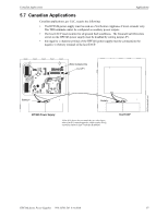
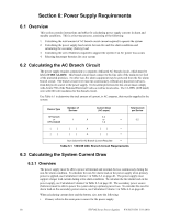
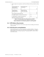
Section 6: Power Supply Requirements 6.1 Overview This section contains instructions and tables for calculating power supply currents in alarm and standby conditions. This is a four-step process, consisting of the following: 1. Calculating the total amount of AC branch circuit current required to operate the system 2. Calculating the power supply load current for non-fire and fire alarm conditions and calculating the secondary (battery) load 3. Calculating the size of batteries required to support the system if an AC power loss occurs 4. Selecting the proper batteries for your system 6.2 Calculating the AC Branch Circuit The power supply requires connection to a separate, dedicated AC branch circuit, which must be labeled FIRE ALARM. This branch circuit must connect to the line side of the main power feed of the protected premises. No other non-fire alarm equipment may be powered from the fire alarm branch circuit. The branch circuit wire must run continuously, without any disconnect devices, from the power source to the power supply. Overcurrent protection for this circuit must comply with Article 760 of the National Electrical Codes as well as local codes. Use 14 AWG (2.00 mm2) wire with 600 volt insulation for this branch circuit. Use Table 6.1 to determine the total amount of current, in AC amperes, that must be supplied to the system Device Type Number of Devices Current Draw (AC amps) Total Current per Device HPF24S6/8 3.2 or 1 X or HPF24S6/8E 1.6 = 3.2 [ ] [ ] X [ ] = [ ] [ ] X [ ] = Sum Column for AC Branch Current Required = Table 6.1 120/240 VAC Branch Circuit Requirements 6.3 Calculating the System Current Draw 6.3.1 Overview The power supply must be able to power all internal and external devices continuously during the non-fire alarm condition. To calculate the non-fire alarm load on the power supply when primary power is applied, use Calculation Column 1 in Table 6.3 on page 40. The power supply must support a larger load current during a fire alarm condition. To calculate the fire alarm load on the power supply, use Calculation Column 2 in Table 6.3 on page 40. The secondary power source (batteries) must be able to power the system during a primary power loss. To calculate the non-fire alarm load on the secondary power source, use Calculation Column 3 in Table 6.3 on page 40. When calculating current draw and the battery size, note the following: • Primary refers to the main power source for the power supply. 38 HPF24S Series Power Supplies - P/N 52751:D3 5/11/2010
-
 1
1 -
2
-
3
-
4
-
5
-
6
-
7
-
8
-
9
-
10
-
11
-
12
-
13
-
14
-
15
-
16
-
17
-
18
-
19
-
20
-
21
-
22
-
23
-
24
-
25
-
26
-
27
-
28
-
29
-
30
-
31
-
32
-
 33
33 -
 34
34 -
 35
35 -
 36
36 -
 37
37 -
 38
38 -
 39
39 -
 40
40 -
 41
41 -
 42
42 -
 43
43 -
44
-
45
-
46
-
47
-
48
-
49
-
50
-
51
-
52
 |
 |
